www.roadwidener.com
34
Model SP-8 &10
31. Apply lubrication to inside tubes welded to
moveable section for ease of operation.
32. Remove loop hose (Y) from left side bulkhead
ttings. Connect marked hoses (A) and (B) for
“extend” and “retract” ports on respective bulkhead
ttings. Hose ends with 90° bend connect to
bulkhead ttings.
33. On right side bulkhead ttings (D), remove cap
ttings and use loop hose (Y) to connect the
“extend” and “retract” ports.
34. On left side blade assembly, mount hoses (A) and
(B) to blade sections by mounting hose clamps to
welded studs (F). Leave enough hose length near
blade column to compensate for blade swing.
35. Connect marked hoses (A) and (B) to “extend”
and “retract” port ttings (E) on hydraulic extension
cylinder.
^ WARNING
Pressurized uids can penetrate the skin.
Hydraulic hoses can fail from age, damage
and exposure.
Do not search for hydraulic leaks without
body and face protection. A tiny, almost
invisible leak can penetrate the skin,
thereby requiring immediate medical
attention.
Use wood or cardboard to detect hydraulic
leaks, never use your hands.
36. Start machine.
37. Raise left side blade assembly and test hydraulic
extension by toggling extend button both ways
on operator console. Check for leaks at hose
connections between hydraulic extension and
bulkhead ttings.
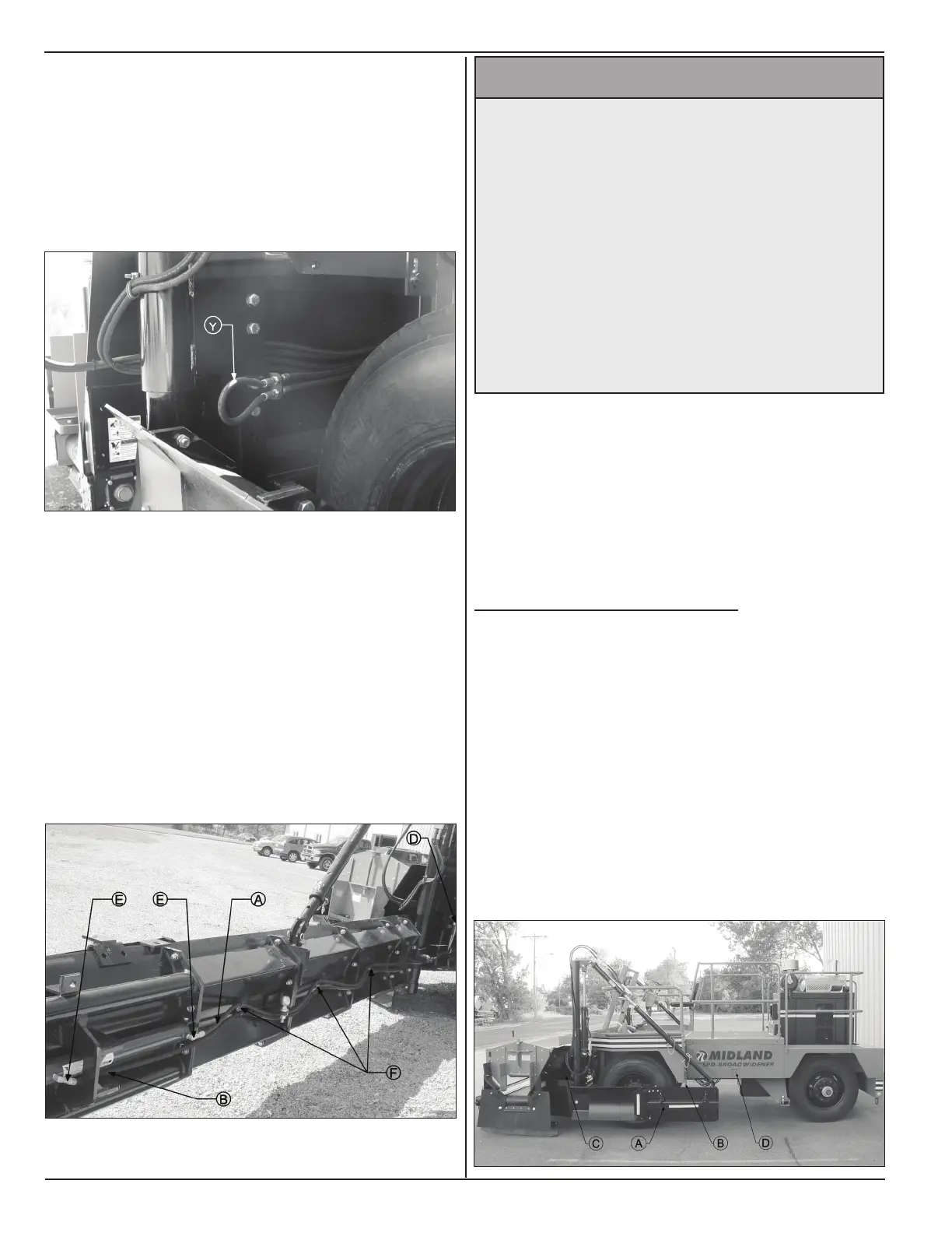
5.8 loAdInG for trAnsport
1. Conrm that both right and left side blade
assemblies (A) are folded and positioned parallel
to length of machine.
2. Conrm that both right and left side blade
assemblies are constrained to chassis by blade
constraint assemblies (B).
3. Store push tubes and outer edger brace in storage
area (C) and tie them to oor with cable ties.
4. Make sure that side access door (D) is secured
tight.