25
www.roadwidener.com
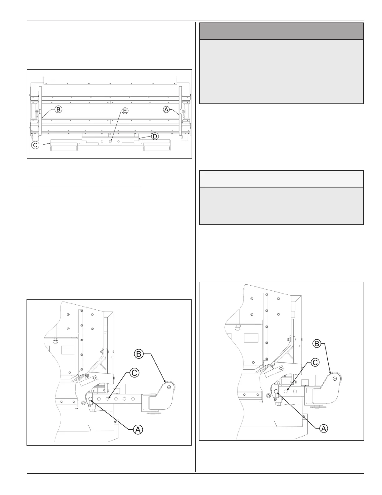
Model SP-8 & 10
For dual sided machine, pivot hole on push roller beam
(C) must be in-line with center hole on push roller
mount (D).
Pivot pin (E) must be inserted through the in-line holes.
5.4.2 pusH roller dIstAnCe setup
Set push rollers at proper distance for trucks being
used. Correct distance is needed so the material does
not spill on the road or dump on hopper back.
1. Release the locking pins (A) at the mount tubes
under the hopper.
2. Carefully pull out push rollers (B) out to the last pin
hole. Count visible holes (C) on push roller mount
tube. If 5 holes are visible, the push roller is on last
hole.
^ WARNING
Prevent serious injury or death.
Do not pull out push roller beyond 6th
hole.
Push roller assembly may fall out of tubes
and cause injury.
3. Have dump truck back up towards hopper or move
machine forward until truck tailgate position is such
that with tailgate locked, material should dump in
center of the hopper, not on road or back of hopper.
There should be at least 6 inch clearance above
belt for tailgate.
NOTICE
Prevent equipment damage.
Do not allow truck tailgate to contact
conveyor belt. Serious damage will result.
4. Truck’s rear tires will move push rollers back to
correct position
5. Pull truck forward and replace locking pins (A) to
the nearest pin hole (C).