www.roadwidener.com
40
Model SP-8 &10
8. Loosen jam nuts (F) on all four square head cap
screws (G).
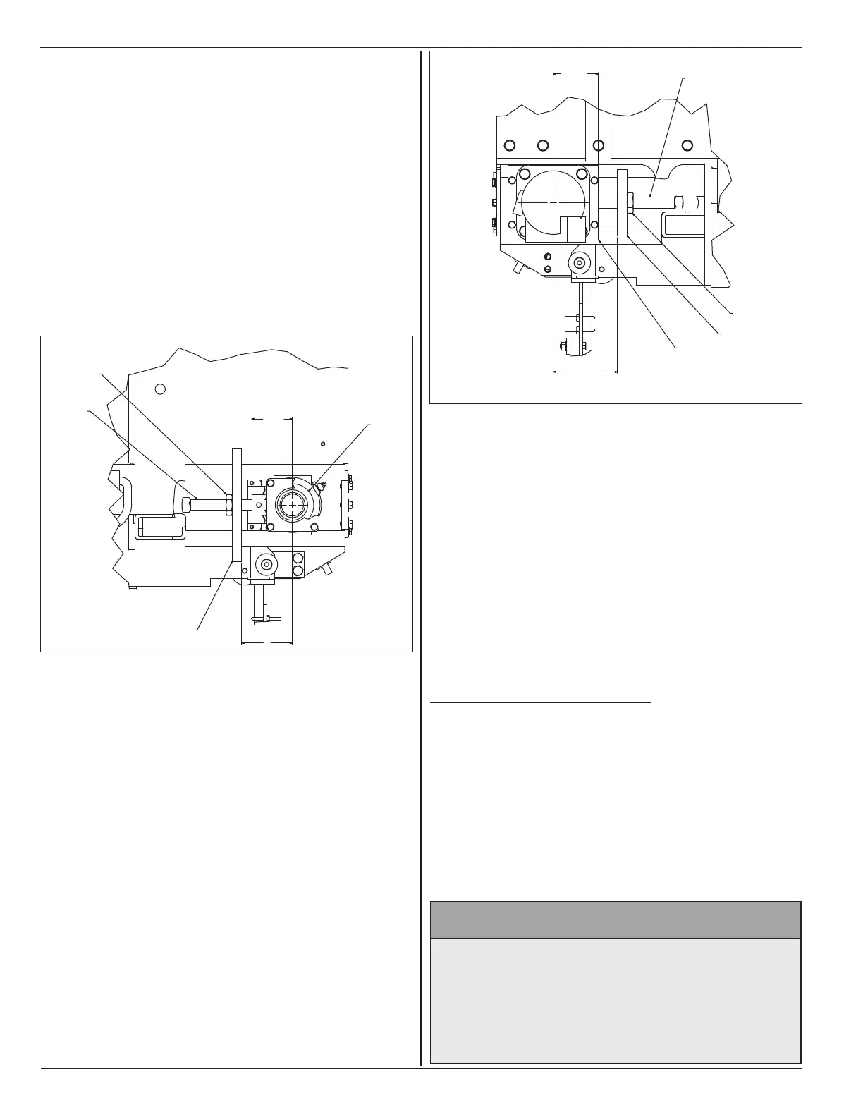
9. On hopper back side of both discharge ends,
measure distance “H” between mounting block (J)
and center of take-up bearing (K).
10. For conveyor belt to be centered left to right in
hopper frame, distance “H” must be same on both
discharge ends.
11. On hopper back side of both discharge ends, turn
square head cap screws (G) to make distance “H”
same.
12. On hopper front side of both discharge ends,
measure distance “L” between mounting block (M)
and center of motor mount (N). On non-discharge
end of single sided machine, “L” is the distance
between mounting block “M” and center of take-up
bearing.
13. On hopper front side of both discharge ends, turn
square head cap screws (G) to make distance “L”
same.
14. On each discharge end, formula for correct
alignment of drive roller with the conveyor belt is
L = H+1
15. Adjust square head cap screws (G) to obtain
distance “L” and “H” as in step 14.
3 1/4
REF
H
F
G
J
K
HOPPER BACK SIDE
16. Turn four square head cap screws (G) equally to
move drive rollers outward.
17. Check conveyor belt tension by measuring distance
“A” as in step 1 and running belt as in steps 3-6.
18. Tighten jam nuts (F) against all mounting blocks.
19. On non-discharge end, re-install bib assembly on
dual sided machine. On single sided machine re-
install end plate.
6.3.2 replACe Conveyor Belt
Following section illustrates steps involved in
replacement of conveyor belt on SP-8 & 10 machines.
These steps should be followed to replace belt if wear
is visible on belt, or there is visible wear of splice hinge.
It is required that suitable lifting equipment is available
to lift and move hopper components. An overhead
crane use is recommended.
^ WARNING
Prevent serious injury or death.
Conveyor Belt and end gates are heavy.
Use an adequate lifting device to raise, lift
and move Conveyor belt and end gates.
3 9/16
REF
L
M
N
F
G
HOPPER FRONT SIDE