www.roadwidener.com
26
Model SP-8 &10
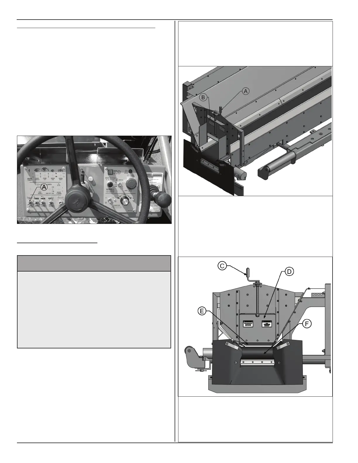
5.4.3 HydrAulIC pusH roller dIstAnCe setup
1. Start machine as in section 5.2.
2. Have dump truck back up towards hopper until truck
tailgate position is such that with tailgate locked
material should dump in center of the hopper ,
not on road or back of hopper. There should be a
minimum of 6 inch clearance above belt for tailgate.
3. Toggle push roller switch (A) to move push roller
beam forward until push rollers touch rear tires of
dump truck.
5.5 set Hopper GAtes
^ WARNING
Prevent serious injury or death.
Before performing inspections, service or
maintenance:
• Park machine on rm, level surface and
engage parking brake.
• Switch engine off.
• Close and lock control panel cover.
• Chock tires.
Procedure illustrated here is for dual sided machine
with optional end gate assemblies to control material
ow at discharge end. Instructions are same for single
sided machine with one end gate assembly.
1. Park machine on a rm level surface, engage
parking brake by pushing E-stop button operator
console fully down.
2. Switch engine off
3. Close and lock control panel cover.
4. Turn crank (A) clockwise on desired side of hopper
to lift gate (B) as high as required for sufcient
material ow.
5. On opposite end gate assembly in hopper, turn
crank (C) counterclockwise to lower gate (D).
6. Lower gate (D) until the gap between rubber seal
(E) and conveyor belt (F) is approximately 1/4 inch.