33
www.roadwidener.com
Model SP-8 & 10
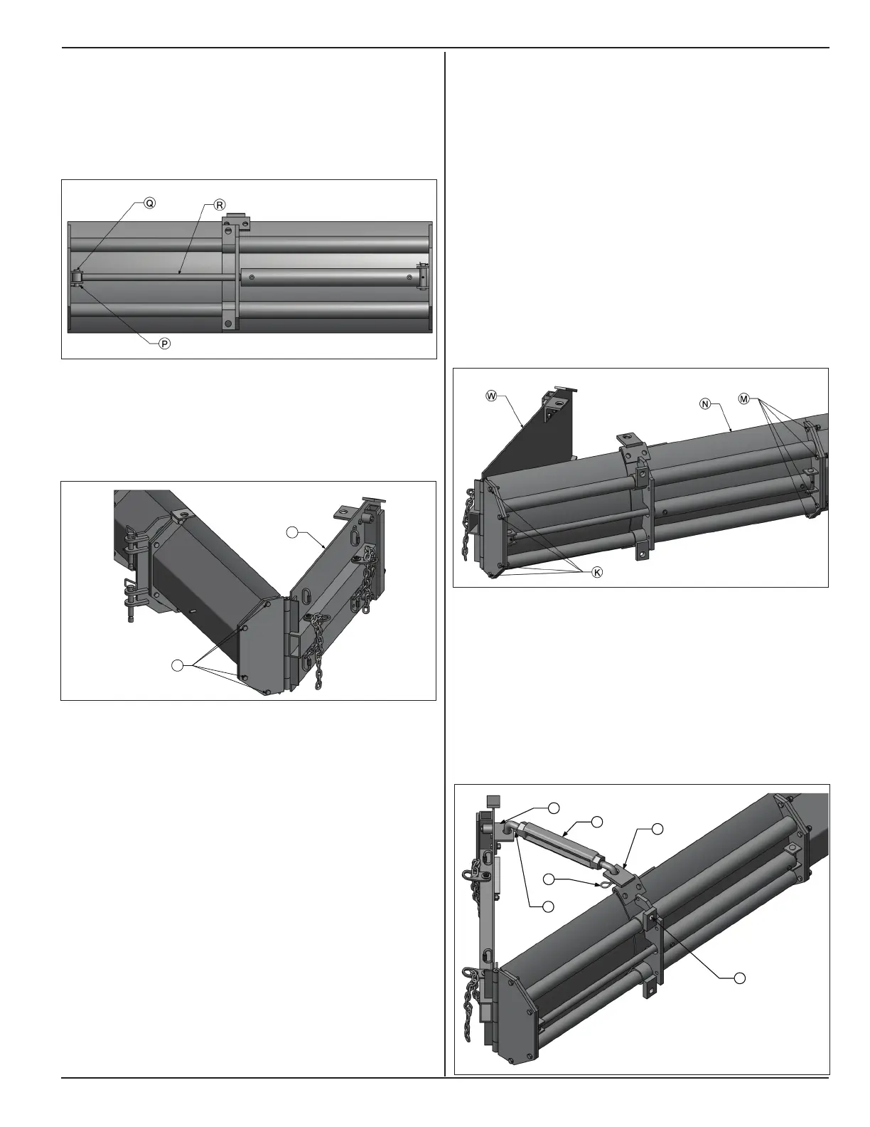
17. Push in moveable section of hydraulic extension
till the sleeve of hydraulic cylinder rod (R) is in-line
with the mounting brackets.
18. Insert hinge pin (Q) through the in-line holes and
insert cotter pin (P) to secure it
19. Mount right side outer edger assembly (L) to
outermost blade section on right side blade
assembly using hardware (K). Tighten cap screws
to 60 lb/ft of torque.
20. Repeat steps 6 to 16 in section 5.7.2 to tuck outer
edger assembly to blade assembly and constraint
blade assembly to machine.
21. Toggle conveyor direction switch on operator
console to left side.
22. On left side set up blade assembly position as in
section 5.3.1.
23. Lower blade assembly to ground by toggling grade
switch.
24. Switch engine off.
25. Close and lock control panel cover.
26. Remove left side outer edger assembly (W) from
outermost blade section. Use suitable lifting device
to separate outer edger assembly.
27. Use suitable lifting device to lift hydraulic extension
(N) and bolt its xed section to outermost blade
section on left side with the help of mounting
hardware (M). Tighten cap screws to 60 lb/ft torque.
Note: In this scenario, bottom edges of hydraulic
extension on right side become top edges on left side.
28. Bolt left side outer edger assembly (W) to moveable
section of hydraulic extension with mounting
hardware (K). Tighten cap screws to 60 lb/ft of
torque.
29. Insert ends of outer edger brace (H) into turnbuckle
mounts (J) and (T). Insert cotter pins (G) to secure
outer edger brace. Rotate turnbuckle to make
outer edger parallel to inner edger.
30. If slope tube is required to be installed on xed
section of hydraulic extension, use mounting hole
(X)
 Loading...