www.roadwidener.com
32
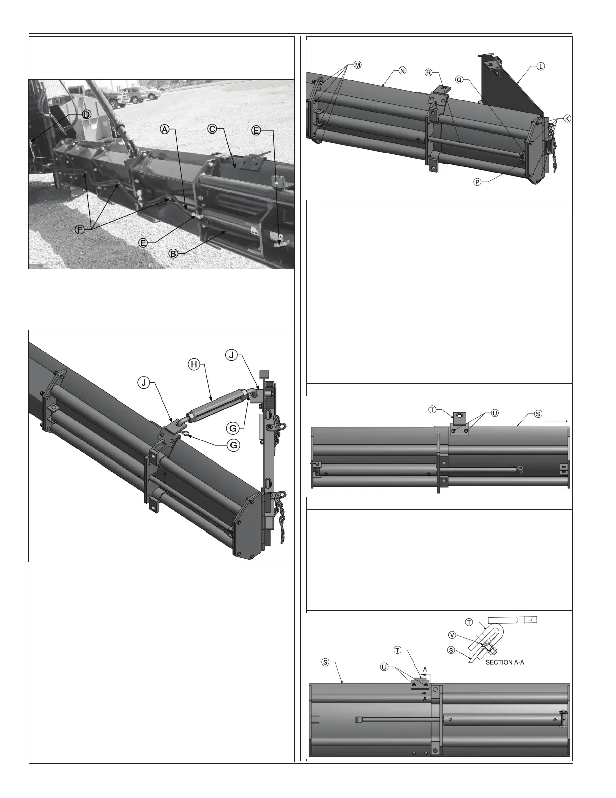
Model SP-8 &10
9. Dismount hoses from blade sections by unbolting
hose clamps from welded studs (F).
10. Remove cotter pins (G) to disengage outer edger
brace (H) from turnbuckle mounts (J).
11. Remove mounting hardware (K) to dismount right
side outer edger assembly (L) from moveable
section of hydraulic extension.
12. Remove mounting hardware (M) to dismount
hydraulic extension (N) from right side blade
assembly.
13. Remove cotter pin (P) to remove hinge pin (Q). This
will disengage the rod end of hydraulic cylinder (R)
from moveable section of hydraulic extension (N).
14. Pull the moveable section (S) of hydraulic extension
out till mounting hardware (U) for turnbuckle mount
(T) are visible.
Note: Do not remove the moveable section of hydraulic
extension completely from the xed section. Guide
tubes will spring out. It will be difcult to align them with
outer tubes on xed section during re-assembly.
15. Remove mounting hardware (U) to dismount
turnbuckle mount (T).
16. Re-install turnbuckle mount (T) in mirrored position
on bottom two holes on moveable section using
mounting hardware (U). Flat head side of bolt (V)
must be towards convex side of the curved part
and ush with outer surface.
 Loading...