23
www.roadwidener.com
Model SP-8 & 10
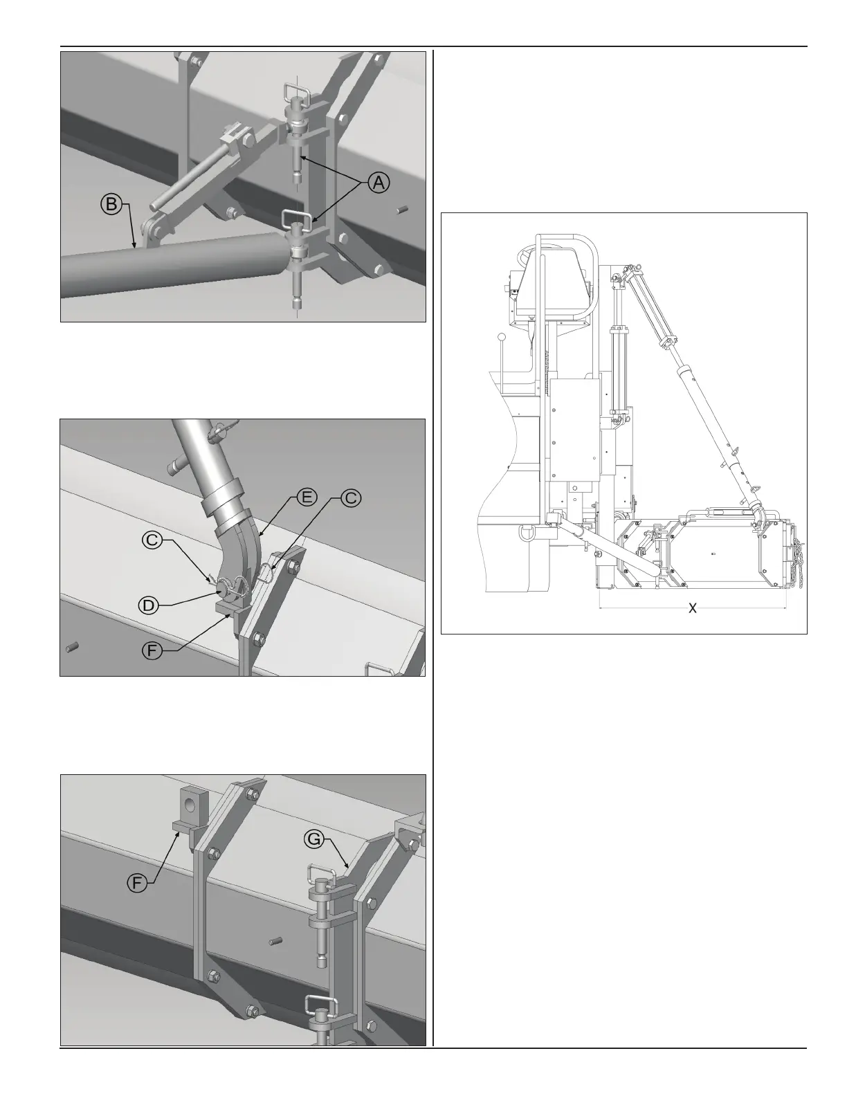
7. Pull out cotter pins (C) and remove hinge pin (D) to
disengage end of lower slope tube (E) from slope
mount (F).
8. Unbolt Blade slope mount (F) and push tube
mounting bracket (G).
9. Set blade length to desired paving width by adding
or removing 1 foot and 2 foot sections. Blade
length should be such that desired paving width is
achieved when blade is set at approximately at 45°
angle to direction of travel.
Following illustration shows different combinations of
blade sections.
Dimension X: 4 Ft Blade
• (1) - Pivot Section
• (1) - 1 Ft Section
• (1) - 2 Ft Section
Dimension X: 7 Ft Blade
• (1) - Pivot Section
• (2) - 1 Ft Section
• (2) - 2 Ft Section
Hydraulic extension (option) can be used to hydraulically
increase overall blade length by up to 2 feet.
Note: Hydraulic extension must be mounted at farthest
end of blade. Moveable section of hydraulic extension
must always extend toward outer edger assembly.
Only outer edger assembly can be bolted to moveable
section of hydraulic extension.
 Loading...