www.roadwidener.com
92
Model SP-8 &10
notes:
Following apply to sections 6.1 To 6.8
1. Used on SP S/N 462 on up and 1052 on up.
2. Wires 18 & 20 are connected when the dual sided discharge option is used.
3. The latching relay is shown with the reset relay energized last.
4. The Ramsey Auto Grade and Slope uses NPN transistors. Therefore the controllers operate the solenoids
by completing (seeking) ground.
5. For the caneld connector LED to light properly, the black wire must be connected to positive voltage.
6. Switch ratings, ref:
32NT91-7 28 VDC, 18A
32NT91-3 28 VDC, 20A
4NT91-3, 28 VDC, 20A
7. The harness, SP-1800-kit, is used on S/N 417 on up and 1044 on up.
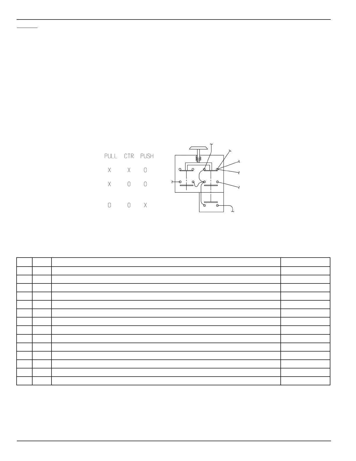
8. Following are the contact positions for brake switch
NO REQ DESCRIPTION PART NUMBER
1 1 HORN, 12 VDC (20/PK) M18031
2 1 BACK-UP ALARM M18100
3 1 BOLTS, BATTERY HOLD-DOWN, (2) 10” J-HOOKS W/ HARDWARE M5055
4 1 BATTERY HOLD DOWN, ADJ, 5-1/2”-9”, RAISED VENT BATTERY M6123
5 1 BATTERY, 12V, 675 CCA, GROUP 24 (SEE ADDED NOTES) M6471
6 6 TUBE CLIP, SINGLE-1 INCH TC-1
7 3 TUBE CLIP, DOUBLE-1-1/4 INCH FOR 3/4 HOSE TCD-1-1/4