VetPro DC Installation/Service Manual, 00-02-1606, Revision R01
45
Line Power,
Cord-
Connected
Installation
1. Using a 3 mm hex key, remove the power line terminal strip cover at the base of
the Power Supply Control Board to gain access to the power line terminal strip, as
shown in
Figure 33.
2. Connect the flanged spade lug of the hot (black) wire of the power cord to the
connection identified as LINE on the power strip.
3. Connect the flanged spade lug of the neutral (white) wire of the power cord to the
connection identified as NEUT on the power strip.
4. Connect the flanged spade lug of the ground (green) wire of the power cord to the
connection identified as GND on the power strip.
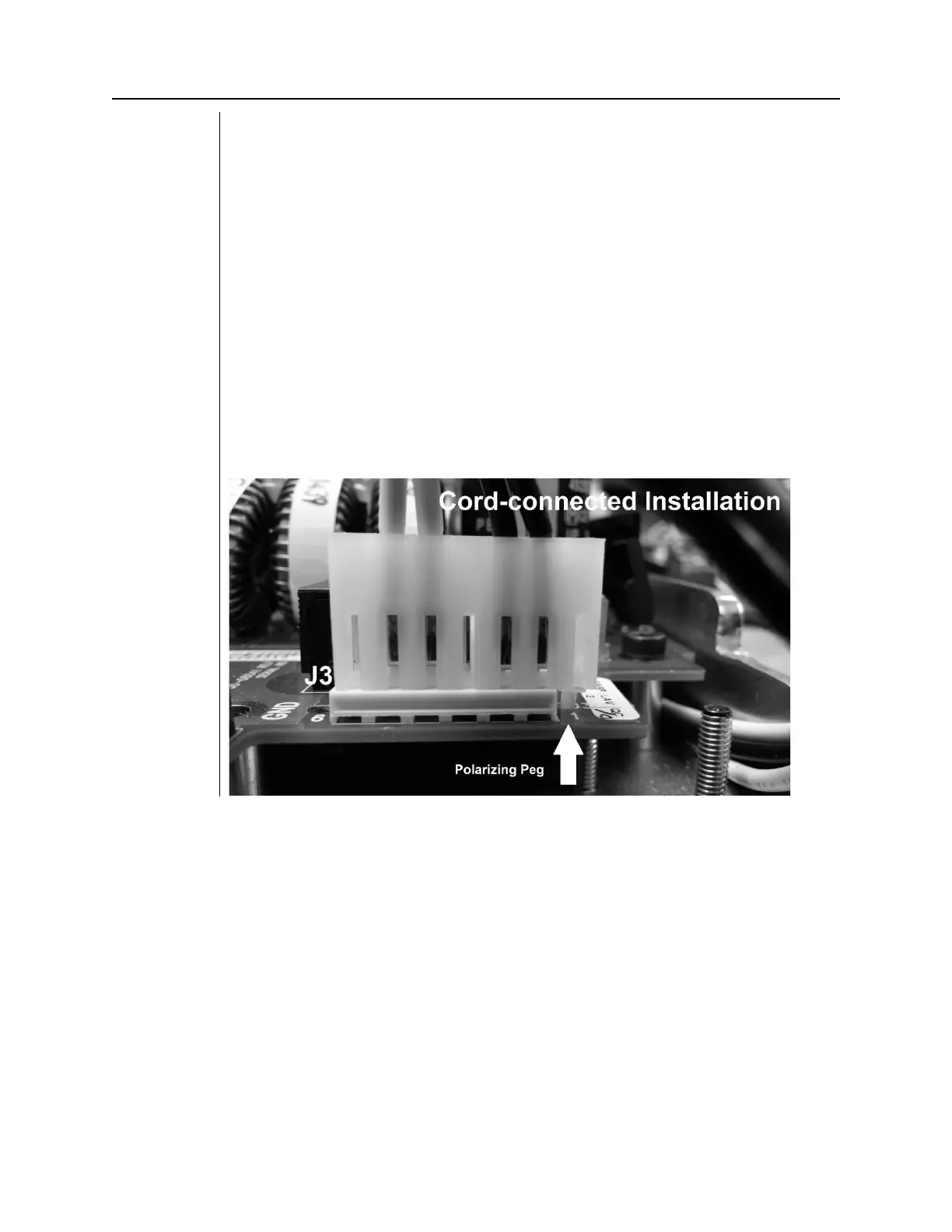
5. Remove the connector from the power switch harness at J3 of the Power Supply
Control Board.
6. Remove the Polarizing Peg from position 7 of the connector. Use a needle nose
plier to rotate the polarizing peg 45 degrees and pull to remove it.
7. Insert the polarizing peg into position 1 of the connector.
8. Reconnect the connector to J3 of the Power Supply Control Board. Align the
polarizing peg as shown in Figure 31.
9. Attach the bracket and strain relief as shown in
Figure 32
.
10. Leave the power line terminal strip cover off until the following electrical
verification procedure is complete.
Figure 32
Power Switch
Harness
Configuration
for Cord-
Connected
Installation