VetPro DC Installation/Service Manual, 00-02-1606, Revision R01
44
Line Power,
Permanently
Wired
Installation
1. Using a 3 mm hex key, remove the power line terminal strip cover at the base of
the Power Supply Control Board to gain access to the power line terminal strip, as
shown in
Figure 33.
2. Attach the hot (black) wire of the mains to the connection identified as LINE on the
power strip.
3. Attach the neutral (white) wire of the mains to the connection identified as NEUT
on the power strip.
4. Attach the ground (green) wire of the mains to the connection identified as GND
on the power strip.
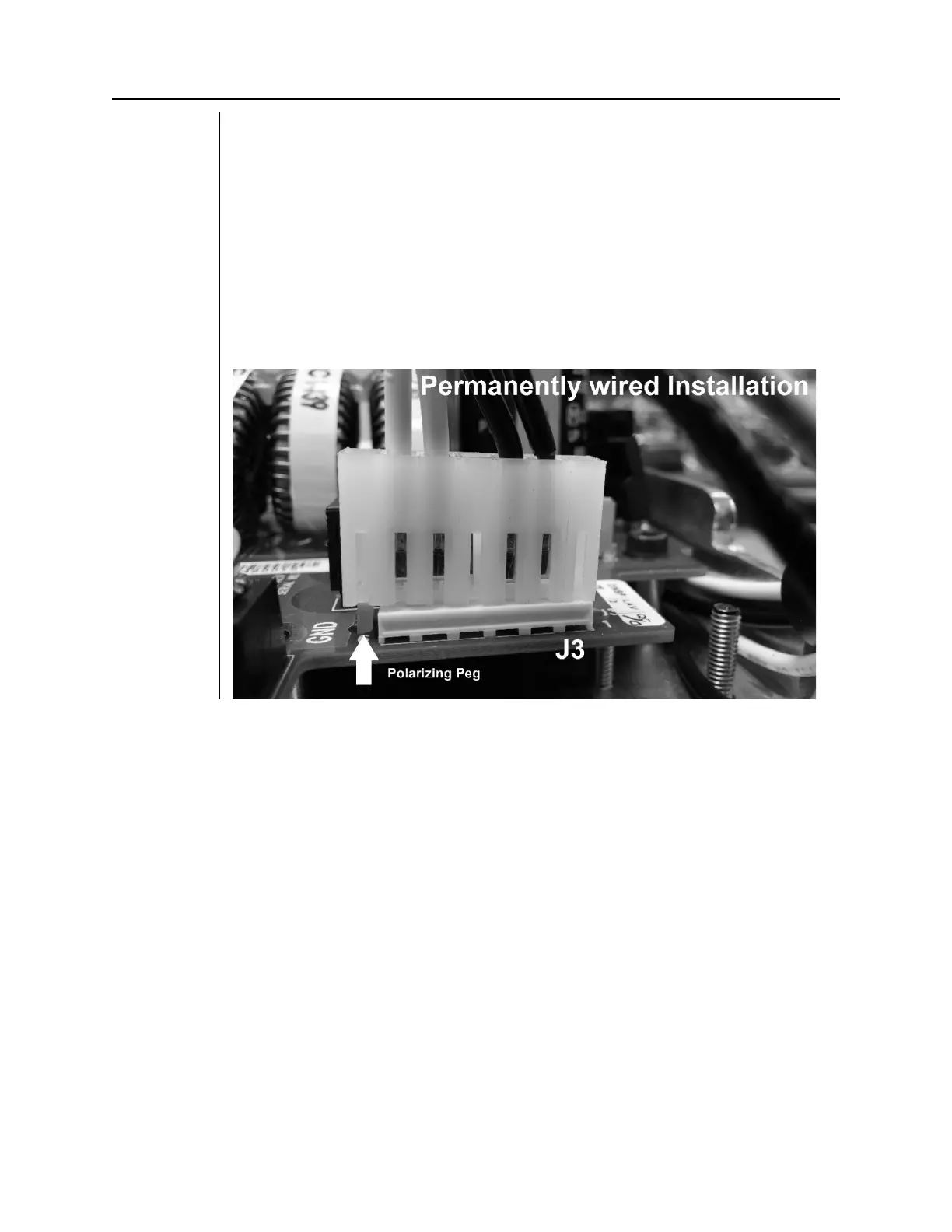
5. The connector from the power switch harness at J3 of the Power Supply Control
Board should be left in the default position as shown in Figure 30.
6. Leave the power line terminal strip cover off until the following electrical
verification procedure is complete.
Figure 31
Power Switch
Harness
Configuration
for
Permanently
Wired
Installation