Pneumatic Circuit System Problems Repair and Troubleshooting
5 - 48 046-001141-00 A5/A3™ Service Manual
Test procedures:
1. Turn off the system switch.
2. Remove the vaporizer.
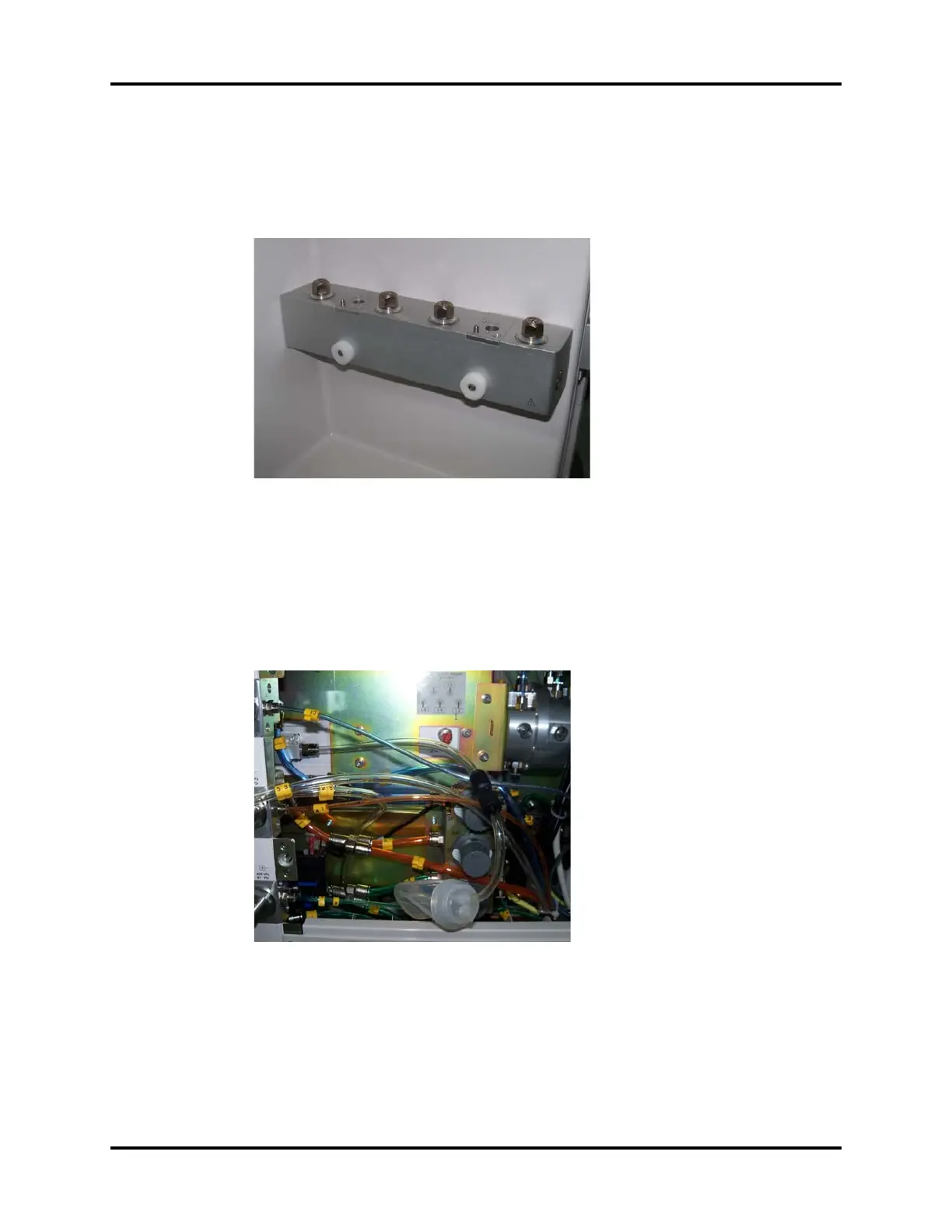
FIGURE 5-49
3. Pull out No.25 PU tube which connects the total flowmeter to the vaporizer manifold assembly.
Disconnect at the vaporizer manifold end and occlude it with 3126-08-00 tube plug
4. Pull out No.53 PU tube which connects the vaporizer manifold assembly to the CGO assembly.
The end of the tube which connects the vaporizer manifold assembly is pulled out, and
connected with the negative ball through one 3106-06-08 adapter connector
5. Flatten the negative pressure ball to remove the gas inside.
FIGURE 5-50
6. Release the negative pressure ball. If the negative pressure ball is fully expanded within 30s, it
indicates that the rubber plain washers or its upper surface contacted mechanical surface are
damaged. Handle this problem as described in the troubleshooting table. If not, continue the
following tests.
7. Remove the seal ring, and mount the vaporizer manifold test fixture onto the connector of the
vaporizer manifold assembly (remove the seal between the connector and the vaporizer when
mounting the test fixture)