A5/A3™ Service Manual 046-001141-00 1 - 23
Theory of Operation Gas Flow
1.3.4.2 Gas Supplies
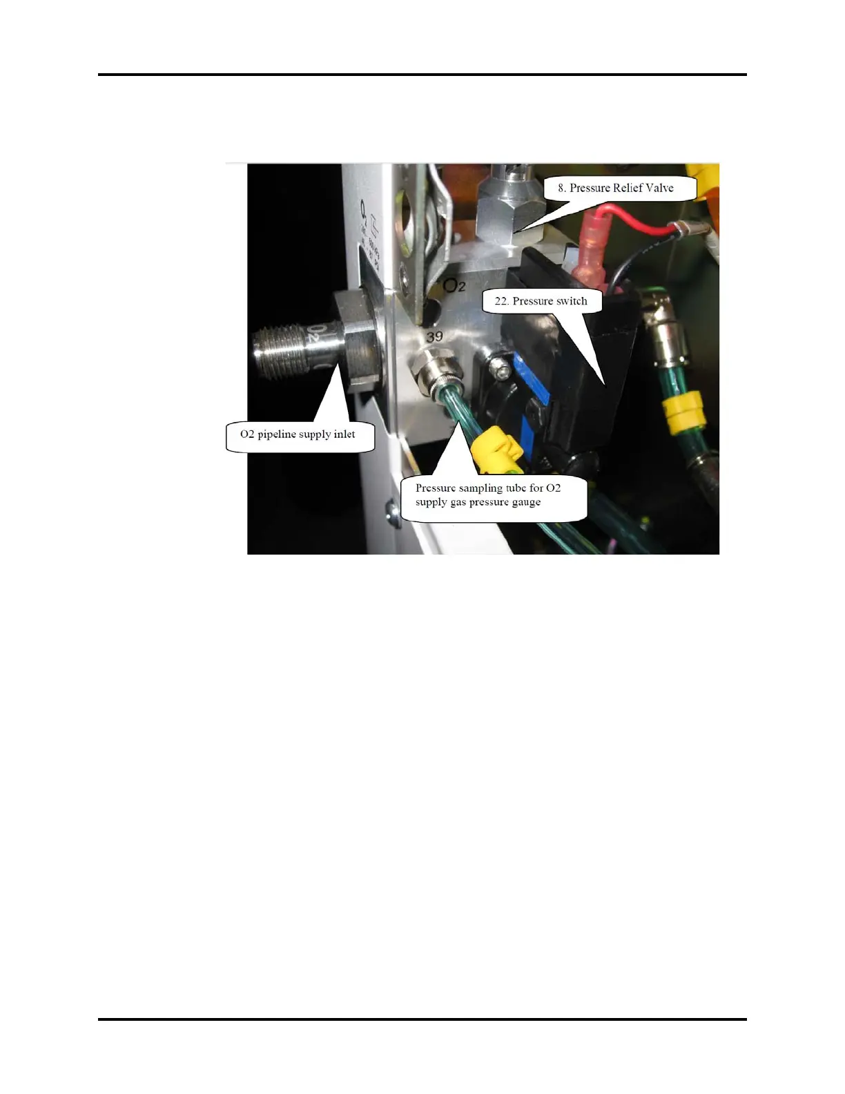
FIGURE 1-11 O2 Pipeline Supply Inlet Assembly
The above picture shows the O2 pipeline supply inlet assembly. The anesthesia machine's pneumatic
circuit starts from the gas supplies, which function to introduce the external pipeline or cylinder
gases into the machine. Since the pressure of external gas is very high and the external gas contains
foreign substances, the pressure reducing valves, filters, and pressure relief valves are available in the
supply gas circuit. Also, the check valves are equipped in the supply gas circuit to prevent gas from
flowing back into the pipeline or cylinder.
The anesthesia machine has pipeline and cylinder gas supplies available. Pipeline gas supplies go
into the pipeline gas supply inlet assemblies through pipeline connectors 1, 3, and 5, respectively.
The pipeline pressure ranges between 280 and 600 kPa. Cylinder gas supplies go into the system
through cylinder connectors 2, 4, and 6, respectively. The O2 and Air cylinder pressures are 6.9 to 15
MPa, and the N2O cylinder pressure is 4.2 to 6 MPa, both of which are decreased to 400 kPa through
three regulators (7). Each connector is clearly marked and designed to prevent misconnection. All
connectors have filters and check valves. Color coded gauges show the pipeline and cylinder
pressures. The Pressure Relief Valve (8) functions to prevent the supply gas pressure from being too
high. It releases excess gas when the gas pressure exceeds 758 kPa. Each supply gas is outputted after
gas pressure is decreased below 200 kPa through the regulator (23). The Pressure Switch (22)
monitors the O2 supply pressure. When the O2 supply pressure is less than approximately 220 kPa,
the ventilator gives an alarm indicating O2 supply failure.