Disassemble the Assemblies Repair and Disassembly
6 - 46 046-001141-00 A5/A3™ Service Manual
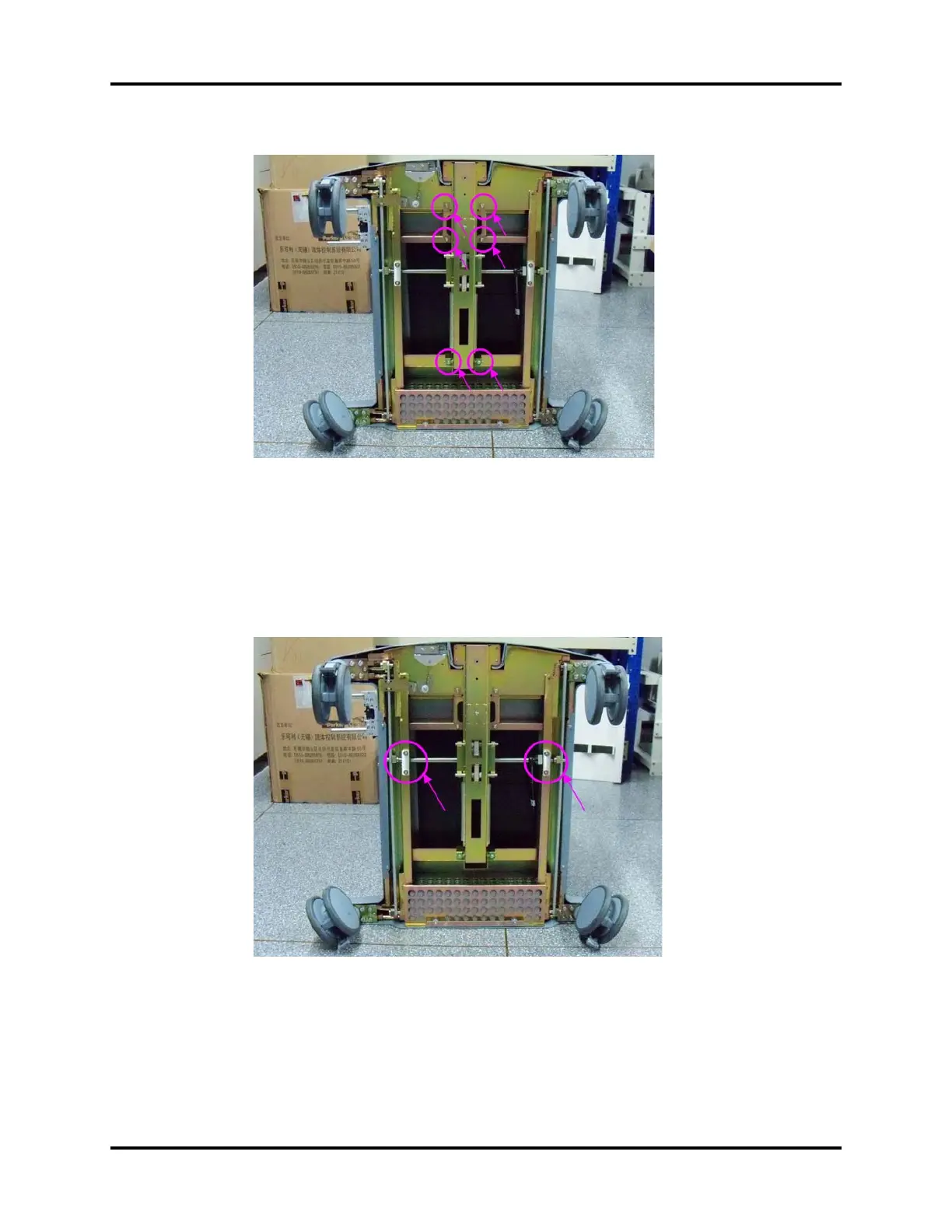
FIGURE 6-87
6.2.11.4 Remove the Brake Main Axis (A5 Only)
1. Tilt A5/A3 backward.
2. Remove brake assembly.
3. Remove the six screws and remove the brake main axis.
FIGURE 6-88
6.2.11.5 Remove the Principal Axis of Brake (A5 Only)
1. Tilt A5/A3 backward.
2. Remove the brake indicator drive plate II.
3. Unscrew the six screws on the brake rod to remove the rod.