A5/A3™ Service Manual 046-001141-00 1 - 29
Theory of Operation Gas Flow
The proportional electromagnetic valve (11) controls inlet gas flow. The filter (9) filters drive gas again.
The regulator (10) regulates pressure inside the pneumatic circuit. Component 12 is a flow sensor of
differential pressure type that monitors gas flow in the drive gas circuit. The Mechanical overpressure
valve (13) ensures that the pressure in the drive gas circuit does not exceed safe pressure. It releases
excess gas when gas pressure exceeds 11 kPa. Component 18 is the expiratory valve. During
expiration, gas inside the bellows is discharged from this valve.
The PEEP function is performed through the expiratory valve. Component 15 is a low-flow
proportional electromagnetic valve. When it opens, gas is bled from the pneumatic resistor (19),
forming relatively stable pressure in the PEEP branch. Such pressure is exerted on the membrane of
the expiratory valve (18) to form PEEP.
To prevent excessively high pressure inside the pneumatic circuit from injuring the patient and
damaging the equipment, the pressure relief valve (15), which is an electromagnetic on-off valve, is
placed before the gas pathway of the expiratory valve. The "16" component is a pressure switch.
When the drive gas pressure is less than 140 kPa, an alarm is triggered. Component 49 is a pressure
sensor that monitors the pressure at which the expiratory valve is closed. The Pressure relief valve (46)
ensures the tube pressure after the expiratory valve is less than 10 cmH2O.
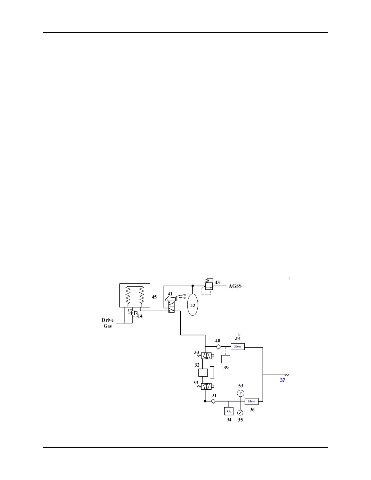
1.3.4.12 Breathing System
The breathing system provides a closed loop for the anesthetic gas. The expired gas from the patient
can be inspired in the inspiration phase to maintain the temperature and humidity conditions of the
patient's expired gas. During inspiration, the drive gas depresses the bag inside the bellows to force
the inside gas to enter the patient's lung. During expiration, the patient's expired gas goes into the
bag inside the bellows. The CO2 Absorber Canister (32) absorbs CO2 that the patient expires. The
following figure shows the pneumatic circuit of the breathing system.
FIGURE 1-20 Breathing System Circuit Diagram