Equipment Views Product Description
2 - 14 Operator’s Manual of Anesthesia System
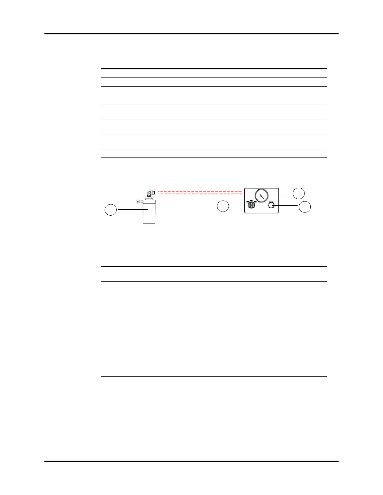
2.2.7 Negative Pressure Suction Device
Figure 2-7 Negative pressure suction device
F3 Expiration connector The expiration connector of the breathing circuit.
F4 Inspiration connector The inspiration connector of the breathing circuit.
F5 Bag arm Used to connect to a manual ventilation bag.
F6 O
2
sensor port Used to install the O
2
sensor to monitor the O
2
concentration.
F7 Canister bypass assembly Used to maintain the pressure in the breathing circuit when
the soda lime in the CO
2
absorbent canister is being replaced.
F8 Watertrap Used to collect the condensate water in the breathing
system. The watertrap must be emptied on a regular basis.
F9 CO
2
absorbent canister The container for holding the CO
2
absorbent (bulk CO
2
absorbent or Pre-pak CO
2
absorbent).
F10 Canister lock A latch to lock (horizontal)/unlock (vertical) the canister.
PARTS DESCRIPTION
PARTS DESCRIPTION
G1 Overfill Protection Prevents the fully collected waste liquid from flowing backward
to ensure the tubing safety.
G2 Negative pressure gauge Indicates negative pressure value.
G3 Negative pressure
adjustment knob
Adjusts the pressure of negative pressure suction device.
G4 Selector switch Switches over between the working modes of the negative
pressure suction device. It can be set to FULL, OFF, or REG. FULL
indicates that the negative pressure suction device is working
with the maximum pressure continuously that is taken from the
wall and the adjustment knob does not function. OFF indicates
that the negative pressure suction device is turned off and is not
working. REG indicates that the negative pressure suction device
works with the pressure adjusted through the negative pressure
adjustment knob. Turn the knob counterclockwise to increase
negative pressure and clockwise to decrease the negative
pressure.