EasyManuals Logo

Mindray SV300 User Manual

Mindray SV300
252 pages
To Next Page IconTo Next Page
To Previous Page IconTo Previous Page
Page #31 background imageLoading...
Page #31 background image
2-5
7. Network connector
A connector which supports connection with a PC to realize software upgrade.
8. RS-232 connector
Connects to the external calibration device for calibrating pressure. An external medical
device can be connected via this connector to communicate with the ventilator.
9. Nurse call connector
Connects to the hospital’s nurse call system and outputs nurse call signals when an
alarm occurs.
10. SpO
2
connector
Connects a SpO
2
sensor to monitor the patient’s pulse and SpO
2
.
11. CO
2
module
Mainstream or sidestream CO
2
module for optional configuration. The connector varies
depending on the configured module.
12. Inlet of high-pressure O
2
supply
13. Inlet of low-pressure O
2
supply
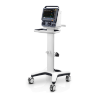
14. Trolley front handle
15. Trolley
16. Equipotential stud / lug
Provides a ground point. Eliminates the ground potential difference between different
devices to ensure safety.

Table of Contents

Questions and Answers:

Question and Answer IconNeed help?

Do you have a question about the Mindray SV300 and is the answer not in the manual?

Mindray SV300 Specifications

General IconGeneral
Waveform DisplayPressure, Flow, Volume
Battery BackupUp to 2 hours
Ventilation ModesVCV, PCV, SIMV
Tidal Volume Range20 to 2000 mL
FiO221 to 100%
Inspiratory Time0.2-5.0 s
Monitoring ParametersPaw, Ppeak, Pmean, Pplat, PEEP, VTI, VTE, MV, f, FiO2, I:E
AlarmsHigh/Low Airway Pressure, High/Low Minute Volume, High/Low Tidal Volume, High/Low Respiratory Rate, High/Low FiO2, Apnea, Power Failure
Power SupplyAC 100-240V, 50/60Hz
Peak Flow180 L/min
Trigger Sensitivity (Flow)0.5-10 L/min