•
•
•
•
•
•
Product presentation
MiR200™ User Guide, Robot interface 2.0, 11/2018 v.1.2 23
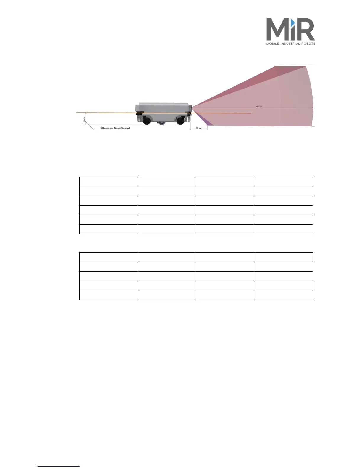
Figure 5.5. The laser scanners detect objects 200 mm above ground and the 3D camera detects objects from ground
level and up to 995 mm above ground
Safety zones
The MiR Safety zones change depending on the speed of the robot.
The speed regulations are as follows for the front scanner:
The speed regulations are as follows for the rear scanner:
The robot uses laser scanner data up to 2.5 m away from the robot for dynamic object identification.
It will actively try to avoid objects within 2.5 m. The scanners will only see objects at 0.2 m height.
No more or less. The scanners can be obstructed by direct sunlight.
Internal
sensors
Internal sensors (see also MiR200™ Inner parts on page 21)
Both gyroscope and accelerometer are placed on the MiR board
Zone name Speed minimum Speed maximum Zone size
Front Field Set 1 -1.4 m/s 0.1 m/s 5 cm
Front Field Set 2 0.11 m/s 0.4 m/s 18 cm
Front Field Set 3 0.41 m/s 0.68 m/s 33 cm
Front Field Set 4 0.69 m/s 1.1 m/s 48 cm
Front Field Set 5 1.11 m/s 2.0 m/s 76 cm
Zone name Speed minimum Speed maximum Zone size
Rear Field Set 1 -0.1 m/s 1.8 m/s 5 cm
Rear Field Set 2 -0.15 m/s -0.2 m/s 14 cm
Rear Field Set 3 -0.21 m/s -0.4 m/s 18 cm
Rear Field Set 4 -0.41 m/s -1.5 m/s 28 cm
• Gyroscope (IMU)
Measures the orientation and angular velocity of the robot.
• Motor encoder
Provides closed loop feedback signals by tracking the speed
and/or position of the motor shaft.
• Accelerometer Measures non-gravitational acceleration
• Wheel encoders Detection of wheel movements
 Loading...


