S2
S1
CONTROLLER
45 OHM
SPEAKER
TO FRONT DOOR
KEYPAD/DISPLAY
RIBBON CABLE
ASSEMBLY
M2
M1
-
+
MIC.
FIG. 10: SPK., MIC., KEYPAD/DISPLAY ASSEMBLY WIRING
GREEN
BLACK & SHIELD
RED
WHITE
20 pins header
MIRCOM TECHNOLOGIES LIMITED, ADC Series: Autodialer Telephone Access Systems Page 17
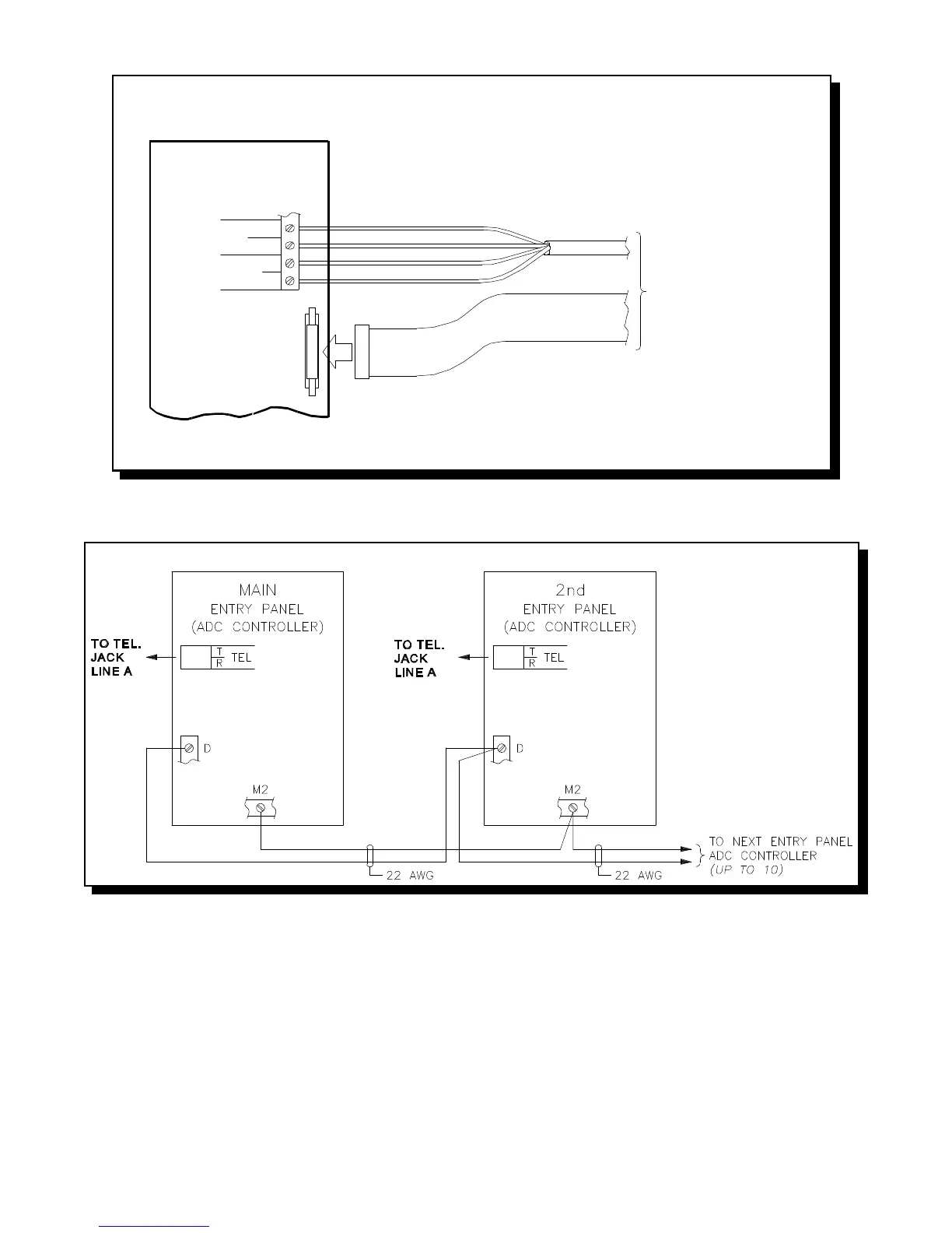
FIG.11: MULTIPLE ENTRANCES and ONE TELEPHONE LINE WIRING
WIRING THE SPEAKER, MIC., and KEYPAD/DISPLAY ASSEMBLY
MULTIPLE ENTRANCES and TELEPHONE LINE WIRING
WIRING THE EARTH GROUND - IMPORTANT NOTICE:
Although the electronics of the ADC Series are not Earth Grounded, it is absolutely vital to have good solid Earth Grounding connections to each
enclosure; that is, a ground bonding wire (preferably at least 14 AWG) that is run to the NEAREST confirmed building electrical system ground, or cold
water pipe. Newer enclosures will have a clearly marked screw connection on the back marked “CHASSIS GROUND”. Older enclosures may be Earth
Grounded via a mounting screw if the enclosure metal under the screw is sanded clean of paint to ensure a good electrical connection.
NOTE: IF PROPER GROUNDING REQUIREMENTS ARE NOT FOLLOWED AS OUTLINED, REPAIRS MAY NOT BE
COVERED BY WARRANTY.
POWERING THE SYSTEM
Before powering the system, double check all the connections. When all connections are checked, power the system up and observe the system display.
If necessary, adjust the contrast as described on Display Contrast Adjustment section.