QAS-2X8 Splitter Configuration - QX-mini and FX-3500 - Two Stage
91
13.3.1 FX-3500 Configuration
Assign the AP Start Range
1. Open the MGC-3000 Series Configuration Utility.
2. Create a new job or open an existing job.
3. Click “Base I/O” in the Job Tree.
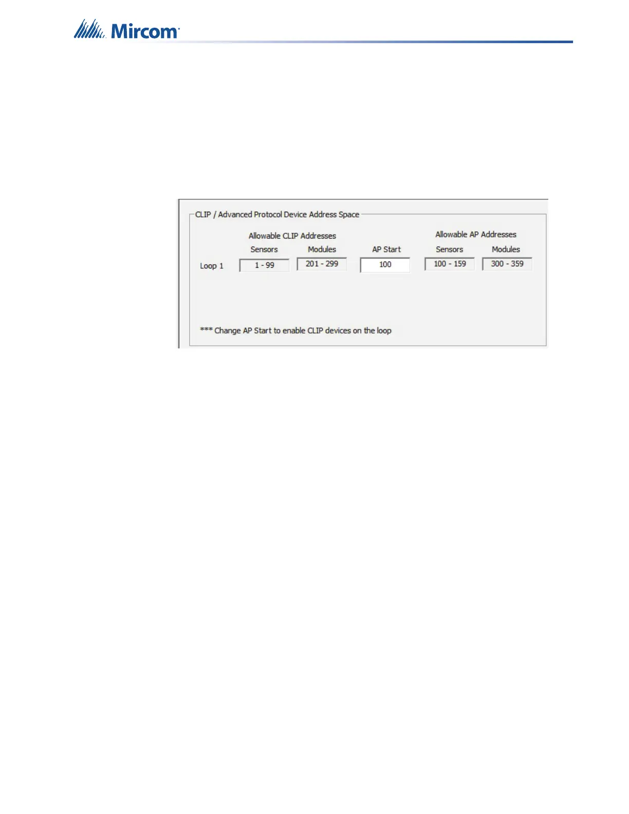
4. Enter “100” in the “AP Start” box to enable CLIP devices on the loop. QX-mini reporting
points are configured as CLIP devices. The “AP Start” number may vary.
Figure 132 CLIP / Advanced Protocol Device Address Space
Note: QX-mini reporting points are configurable in CLIP mode only. It is
important to change AP Start to enable CLIP devices on the loop.
Configure the Output and Input Modules
1. Click the loop that is wired to the SLC terminal on the QX-mini Master.
2. Configure the output modules that will activate functions on the QX-mini, and input
modules that will listen for reporting from the QX-mini. See section 13.4 for details on the
reporting functions.
Table 1 shows an example configuration based on an 8 floor building where during an
alarm, the system provides an alarm signal to 3 floors (the floor of alarm, and the floor
above and below), and an alert signal to the other floors.
Note: These devices are integrated in the QX-mini as virtual devices and do
not need to be physically installed on the loop. The number of virtual
SLC devices depends on your configuration – you can use as many as
your job requires.
The addresses may vary depending on each application. Ensure
supervised output modules and relay output modules to activate QX-
mini zones are configured as shown below.
Note: In this example, CLIP modules range from 201 to 299 on the FX-3500.
On the QX-mini they range from 101 to 199.