B - 119
FX
3S
/FX
3G
/FX
3GC
/FX
3U
/FX
3UC
PLC User's Manual - Positioning Control Edition
Built-in Positioning Functions
A
Common Items
B
Built-in
Positioning
Functions
Apx.
Example
Connection
7 Absolute Position Detection System (Absolute Current Value Read) - ABS Instruction
7.4 Initial Zero Return
- When using the FX2N-1PG(-E), read out the ABS data to the data register first, and then write the read-
out ABS data into the current value register of the FX
2N-1PG(-E) using instructions such as the DTO
instruction.
When using the FX
3U-1PG or FX2N-10PG, either read out the ABS data to the data register first and
write the read-out ABS data into the current value register (value converted into pulse) of the FX
3U-1PG
or FX
2N-10PG using instructions such as the DTO instruction or directly specify the buffer memory
(U\G) for to be written to.
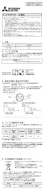
1. Detection of absolute position
1) If the DABS (FNC155) instruction turns ON, the
PLC will activate the servo-ON output and the
ABS transfer mode output.
2) 32+6-bit data communication will be performed
while mutually checking the data sending/
receiving condition using the "send data ready"
signal and the "ABS data request" signal.
3) The 2-bit line (line for ABS bit 0 and bit 1) will be
used for data transmission.
4) At the completion of ABS data reading, the
"Instruction execution complete" flag (M8029)
will turn on.
For details on the "Instruction execution
complete" flag, refer to
Subsection 4.7.4.
7.4 Initial Zero Return
When your system is established, even if your servo motor is equipped with an absolute position detection
function, it is necessary to perform zero return at least once to send the CLEAR signal to the servo motor.
Use one of the following methods for the initial zero return:
1) Execute DSZR (FNC150) with DOG search zero return instruction or ZRN (FNC156) zero return
instruction using the CLEAR signal function to complete zero return.
2) Carry out zero return for the machine using the position adjustment method in the jogging operation mode
or manual operation mode, and then input the CLEAR signal.
To input the CLEAR signal, use the output of the PLC or the external switch shown in the following figure.
D
2
Servo-ON
SON
ABS data transfer
mode
ABSM
ABSR
"Send data ready"
signal
"ABS data request"
signal
ABS(bit1)
ABS(bit0)
Current position data (32 bits)
+ check data (6 bits)
Amplifier output
PLC output
Amplifier output
Amplifier output
ABST
ABS B1
ABS B0
Example for MR-J3
□
A
CR 8
SG 10
Example for MR-J2A
CLEAR
signal
Downloaded from ManualsNet.com search engine

 Loading...