FX
3S
/FX
3G
/FX
3GC
/FX
3U
/FX
3UC
PLC User's Manual - Positioning Control Edition
Built-in Positioning Functions
8 1-Speed Positioning - DRVI/DRVA Instruction
8.2 Drive to Increment - DRVI Instruction
B - 123
A
Common Items
B
Built-in
Positioning
Functions
Apx.
Example
Connection
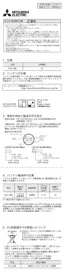
2 : When a high-speed output special adapter is used as a destination for pulse output on a FX3U PLC,
use the output shown in the following table for rotation direction signals.
When a built-in transistor output is used as a destination for pulse output on a FX
3S/FX3G/FX3GC/FX3U/
FX
3UC PLC, use transistor output for signals rotation direction.
For the outputs applicable with a High-speed output special adapter, refer to Section 4.9.
3 : D
.b is available only in FX3U and FX3UC PLCs. However, index modifiers (V and Z) are not available.
4 : Only available for FX
3G/FX3GC/FX3U and FX3UC PLCs.
5 : Only available for FX
3U and FX3UC PLCs.
8.2.2 List of Related Devices
1. Special auxiliary relays
The following table shows the related special auxiliary relays. Note that Y000, Y001, Y002, and Y003 are
devices that determine the pulse output destinations.
High-speed output special
adapter connection position
Pulse output Rotation direction output
1st adapter
= Y000
= Y004
= Y001
= Y005
2nd adapter
= Y002
= Y006
= Y003
= Y007
Device number
Function Attribute Refer to
Y000 Y001
Y002
*1
Y003
*2
M8029 "Instruction execution complete" flag Read only
Subsection
4.4.2
M8329 "Instruction execution abnormal end" flag Read only
Subsection
4.4.2
M8340 M8350 M8360 M8370 "Pulse output monitor" (BUSY/READY) flag Read only
Subsection
4.4.3
M8343 M8353 M8363 M8373 Forward limit Drivable
Subsection
4.3.1
M8344 M8354 M8364 M8374 Reverse limit Drivable
Subsection
4.3.1
M8348 M8358 M8368 M8378 Positioning instruction activation Read only
Subsection
4.4.4
M8349 M8359 M8369 M8379
Pulse output stop command
*3
Drivable
Subsection
4.3.2
*1. Y002 is not available in FX
3G PLC (14-point and 24-point type) and FX3S/FX3GC PLC.
*2. Y003 is available only when two high-speed output special adapters are connected to the FX
3U PLC.
*3. Cleared when the PLC switches from RUN to STOP.
D
2
D
2
D
2
D
2
Downloaded from ManualsNet.com search engine

 Loading...