2Unpacking to installation
2-33
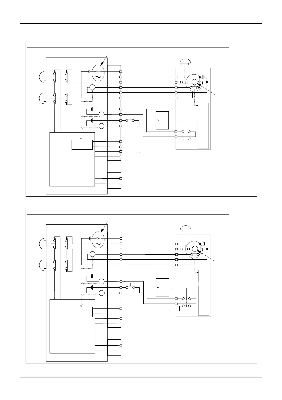
Fig.2-24 : Limitations when connecting the relay etc. (CR750)
Fig.2-25 : Limitations when connecting the relay etc. (CR751)
1
2
3
4
5
6
13
14
11
12
16/17
41/42
CNUSR11/12
CNUSR2
付加軸用コンタクタ
コントロール出力
内部非常停止回路
ロボットコントローラ
未接続
非常停止スイッチ
(2接点タイプ)
エラー出力
モード出力
周辺装置
TB非常停止
ボタン
OP非常停止
ボタン
}
RA
RA
RA
}
}
ロボットコント
ローラ内電源
24V
ドアスイッチ入力
安全柵のドア
イネーブリング
デバイス
周辺装置
側電源24V
監視
監視
周
辺
装
置
側
内
部
回
路
RA
安全リレー
7
8
9
10
F2
F1
The electric-current value limitation when connecting the coils, such as the Relays (CR750 controller)
Relay
Rated-current is 100mA
or less
Note) If you connect the relay etc., rated current of the coil
should use the relay which is 100mA/24V or less.
If the electric current of the further flows, internal fuse 1
may cut. And, although the example of the connection
which uses the external power source is shown in the
figure, if the coil is connected using the internal power
supply of the robot controller, internal fuse 2 may cut.
Internal fuse
Not connected
Door switch input
Safety fence door
Enabling device
Error output
Mode output
Power supply in the
robot controller
Robot controller
OP
Emergency
stop button
TB
Emergency
stop button
Safety relay
Internal emergency
stop circuit
Emergency stop switch
(2- contact type)
Peripheral equipment
Power
supply24V
Contactor control out
-
put for additional axes
Monitor
Monitor
Circuit
Note)
1/6
26/31
2/7
27/32
3/8
28/33
16/17
41/42
CNUSR1
CNUSR2
付加軸用コンタクタ
コントロール出力
内部非常停止回路
ロボットコントローラ
未接続
非常停止スイッチ
(2接点タイプ)
エラー出力
モード出力
周辺装置
TB非常停止
ボタン
OP非常停止
ボタン
}
RA
RA
RA
}
}
ロボットコント
ローラ内電源
24V
ドアスイッチ入力
安全柵のドア
イネーブリング
デバイス
周辺装置
側電源24V
監視
監視
周
辺
装
置
側
内
部
回
路
RA
安全リレー
29/34
30/35
4/9
5/10
20/19
45/44
18/17
43/42
F2
F1
The electric-current value limitation when connecting the coils, such as the Relays (CR751 controller)
Note) If you connect the relay etc., rated current of the coil
should use the relay which is 100mA/24V or less.
If the electric current of the further flows, internal fuse 1
may cut. And, although the example of the connection
which uses the external power source is shown in the
figure, if the coil is connected using the internal power
supply of the robot controller, internal fuse 2 may cut.
Relay
Rated-current is
100mA or less
Internal fuse
Monitor
Monitor
Circuit
Emergency stop switch
(2- contact type)
Peripheral equipment
Power
supply24V
Not connected
Door switch input
Safety fence door
Enabling device
Error output
Contactor control out
-
put for additional axes
Mode output
Power supply in the
robot controller
Robot controller
Safety relay
Internal emergency
stop circuit
OP
Emergency
stop button
TB
Emergency
stop button
Note)
 Loading...


