2-34
2Unpacking to installation
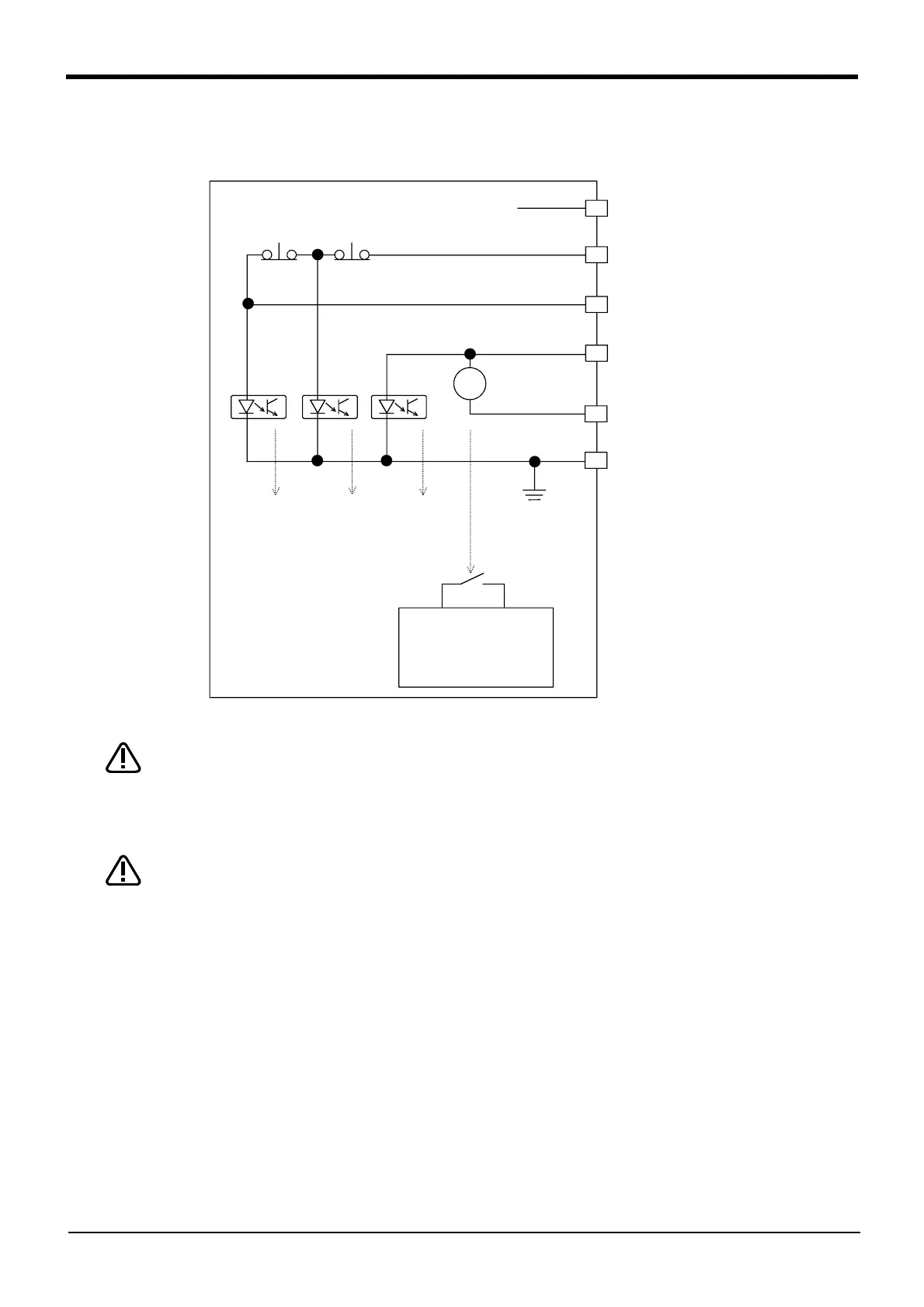
[Supplementary explanation regarding emergency stop circuit]
The controller’s internal circuit is as shown in the below diagram. Be sure to build a circuit that properly
shuts off the emergency stop detection relay when the emergency stop button is pressed.
Be sure to perform wiring correctly. If there are mistakes in the wiring, the robot may
not stop when the emergency stop button is pressed and there will be a risk of damage
or personal injury occurring.
After wiring, be sure to press each of the installed emergency stop switches and check
whether the emergency stop circuit works properly.
Be sure to duplicate connection of the emergency stop, door switch and enabling
switch. If not duplicated, these functions may fail due to a broken relay used by
customer, etc.
OP
非常停止
非常停止検出
リレー
24V
TB
非常停止
+
-
OP
非常停止
検出
TB
非常停止
検出
外部
非常停止
検出
0V
入力
安全リレー
Safety relay
Input
Emergency stop
detection relay
TB
emergency
stop
OP
emergency
stop
OP
emergency
stop
detection
TB
emergency
stop
detection
External
emergency
stop
detection
 Loading...


