9 - 15 9 - 15
MELSEC-Q
9 POSITIONING CONTROL
Restrictions
(1) If "Continuous path control" is set in "
Da. 1
Operation pattern", the "Continuous
path control not possible" error (error code: 503) occurs, disabling a start.
(2) "Speed-position switching control" cannot be set in "
Da. 2
Control method" of
the positioning data if "Continuous path control" is set in "
Da. 1
Operation
pattern" of its preceding positioning data. (For example, if the operation pattern
of positioning data No. 1 is "Continuous path control", "Speed-position
switching control" cannot be set in positioning data No. 2.) If such setting has
been made, the "Continuous path control not possible" error (error code: 503)
occurs, resulting in a deceleration stop.
(3) Under speed control of speed-position switching control, the software stroke
limit range is checked only when "1: Update" has been set in "
Pr. 4
Current
feed value during speed control".
If the movement amount has exceeded the software stroke limit range during
speed control at the setting of other than "1: Update", the "Software stroke limit
+, -" error (error code: 103 or 104) occurs, resulting in a deceleration stop.
(4) If the setting value of "
Da. 6
Positioning address/movement amount" is
negative, the "Setting range outside" (error code: 513) occurs.
(5) If the movement amount of position control set in "
Da. 6
Positioning
address/movement amount" is less than the deceleration distance from "
Da. 5
Command speed", deceleration processing is started at the input of the speed-
position switching signal.
(6) To suppress the variation of the stopping position after switching to position
control, turn ON the speed-position switching signal in the stable speed region
(constant-speed status).
(7) If "0" has been set in "
Pr. 6
Bias speed at start", starting operation at the
setting of "0" in "
Da. 5
Command speed" for speed control of speed-position
switching control will result in the following.
• 0 speed (
Md. 7
Status: b2) turns ON.
• Though the axis is at a stop, "
Md. 4
Axis operation status" is "Speed.Position
Speed" and the BUSY signal remains ON. (Turning ON the axis stop signal
turns OFF the BUSY signal and changes "
Md. 4
Axis operation status" to
"Stopped".)
In this case, setting other than "0" in "
Cd. 7
New speed value" and "1" in
"
Cd. 6
Speed change request" turns OFF 0 speed (
Md. 7
Status: b2),
enabling operation to be continued.
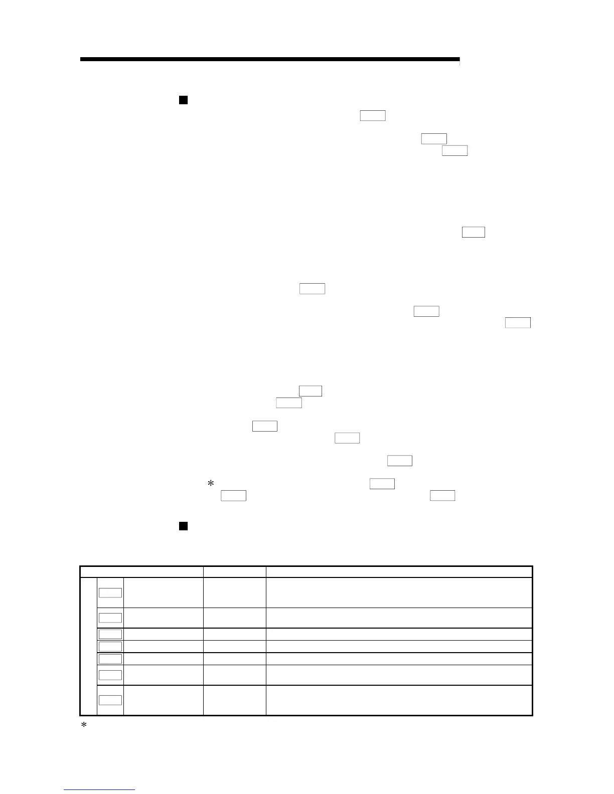
Positioning data setting examples
The following table shows setting examples when "speed-position switching control
by forward run" is set in positioning data No. 1 of axis 1.
Setting item Setting example Setting details
Da. 1
Operation pattern
Positioning
termination
Set "Positioning termination" assuming the next positioning data will not
be executed. ("Continuous path control" cannot be set in "speed-
position switching control".)
Da. 2
Control method
Speed.Position
Ctrl. (Forward)
Set speed-position switching control by forward run.
Da. 3 ACC/DEC time 1000ms
Set the acceleration/deceleration time for speed-position switching control.
Da. 4 DEC/STOP time 1000ms Set the deceleration stop time for speed-position switching control.
Da. 5 Command speed 50000pulse/s Set the speed to be controlled.
Da. 6
Positioning address/
movement amount
10000pulse Set the movement amount after the switching to position control.
Axis 1 positioning data No. 1
Da. 7
Dwell time 500ms
Set the time from when a stop (pulse output stop) is made under
position control until the positioning complete signal is output.
(The setting value is ignored if a stop is made under speed control.)
Refer to "Section 4.5 List of positioning data" for the setting details.
 Loading...