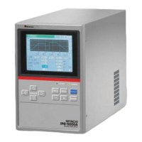
IPB-5000A
10. External Communication Function
10-6
No. Description of Command Code
Reading of Initial Setting # Device No. R Specified Code
6
Example: Read Model of Transformer at Initial Setting (6.(9)STATUS
Screen) in Device No. 01.
From Host PC to IPB-5000A
# ID1 ID2 R CD1 CD2 CD3 CR LF
(# 0 1 R P 4 0 CR LF)
From IPB-5000A to Host PC
! ID1 ID2 CD1 CD2 CD3 : Data CR LF
(! 0 1 P 4 0 : Data CR LF)
Setting of Initial Setting
Condition
# Device No. W Specified Code :
Data
7
Example: Set the time period during which Weld End Signal Time is
output to 100ms (Data is shown as 01) at Initial Setting
(6.(9)STATUS Screen) in Device No. 01.
From Host PC to IPB-5000A
# ID1 ID2 W CD1 CD2 CD3 : Data CR LF
(# 0 1 R P 0 3 : 0 1 CR LF)
From IPB-5000A to Host PC
! ID1 ID2 CD1 CD2 CD3 : Data CR LF
(! 0 1 P 0 3 : 0 1 CR LF)
Reading of monitor data in
specified range
# Device No. ? Specifying of
Range
8
Example: Read monitor data from No. 0001 to 0013 in Device No. 01.
From Host PC to IPB-5000A
# ID1 ID2 ? Start No. – End No. CR LF
(# 0 1 ? 0 0 0 1 - 0 0 1 3 CR LF)
From IPB-5000A to Host PC
! ID1 ID2 Start No. – End No., Data CR LF
(! 0 1 0 0 0 1 - 0 0 1 3 , Data String CR LF)
Note) See (5)②Order Table of Monitor Data for Start No. and End
No.
Reading of Trouble # Device No. R E99
9
Example: Read all troubled items (Error Codes, E02 E05) in Device
No. 01.
From Host PC to IPB-5000A
# ID1 ID2 R CD1 CD2 CD3 CR LF
(# 0 1 R E 9 9 CR LF)
From IPB-5000A to Host PC
! ID1 ID2 SH1 SH2 SH3 : Data CR LF
(! 0 1 E 9 9 : E 0 2 , E 0 5 CR LF)
Note) All error codes are read (Each error code is separated with
“,”).
In no trouble, data of “00”is returned.
(! 0 1 E 9 9 : 0 0 CR LF)