Chassis Information --- Section 10
Cayman 2005
321
AIR SUPPLY SYSTEM
The air compressing system on the motorhome consists of
an air compressor, air governor, and air tank. The compressed
air system operates several items, some of which include: suspen-
sion, an air gauge (depending on options) and stepwell cover. A
gear driven air compressor mounted on the engine charges the
system. As engine speed increases, compressed air output
increases. When air is compressed, heat is generated. Heat dissi-
pates as the air is discharged from the compressor. Moisture
condenses in the compressed air as it cools. Moisture laden air
is released through the automatic drain on the bottom of the air
tank. The air tank is divided in two halves: a wet side and a dry
side. The compressed air enters the wet side before entering the
dry side. The tank is equipped with a pop valve for over-pres-
sure protection, a manual drain valve and automatic drain valve.
The manual drain is located on the DRY side of the tank. The
pop valve and automatic drain valve are located on the WET
side. The pop valve is designed to release pressure in the tank
when the pressure exceeds 130 psi. With the ignition switched
to ON, the automatic drain valve (standard brake models)
wired to the brake light circuit will activate each time the
brakes are applied. Only a small amount of air/water is
expelled. The momentary release of air/water from the tank is audible.
Pneumatically operated items are divided into two categories: brakes and accessory air. Brakes have
full use of supplied air pressure. Accessory air items, such as a stepwell cover, receive air through a pres-
sure protection valve (PPV). The PPV will not allow compressed air flow until approximately 60 psi. In
case of an air system problem, the pressure protection valve will leave a reserve air charge for braking.
Pressure protection valves are installed for safety.
A low-pressure air switch connected to a warning lamp on the dash console monitors the air system.
The lamp will illuminate when a low-pressure condition exists. Check the operation of the low air lamp
when the air tank is drained.
NOTE:
The air tank should be drained manually every 30 days. Open the manual drain on
the bottom of the tank until all air escapes. Leave valve open an additional five
minutes allowing excess moisture to drain.
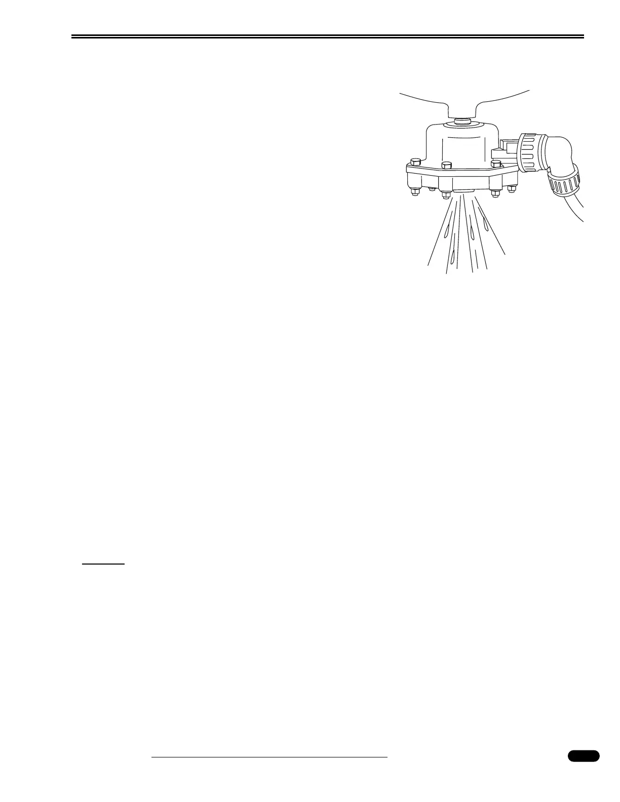
Automatic drain on standard brake models.
040380