TABLE OF FIGURES
Figure 2.1 Moog Curlin Infusion Ambulatory
Pump – Front, Top, and Left View .........15
Figure 2.2 Moog Curlin Infusion Ambulatory
Pump – Back, Bottom, and Right View .....16
Figure 2.3 Sample of Moog Curlin Infusion
Administration Sets ...................................17
Figure 2.4 Spiking the Fluid Container,
Gravity Priming the Set, and Using the Slide
Clamp to Close the Tubing .......................18
Figure 2.5 Moog Curlin Infusion
Administration Set Integral Flow-Stop with
Breakaway Tab ..........................................19
Figure 2.6 Intentionally Opening
the Integral Flow-Stop ..............................19
Figure 2.7 Opening the Pump Door .............20
Figure 2.8 Closing the Pump Door ............... 21
Figure 2.9 Proper Installation of the Moog
Curlin Infusion Administration Set into the
Pump ........................................................23
Figure 2.10 Top Cutaway View of the Moog
Curlin Infusion Pump with Moog Curlin
Infusion Administration Set in Proper
Installation Position ..................................24
Figure 2.11 ....................................................26
Figure 2.12 Universal AC Adaptor ................34
Figure 2.13 Attaching and Removing the
Remote Bolus Cord ................................... 35
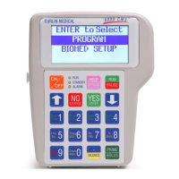
Figure 3.1 Moog Curlin Pump Features ........36
Figure 3.2 Painsmart
™ IOD Keypad with
Info-On-Demand Feature .........................38
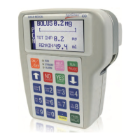
Figure 3.3 Sample of Display Screen ............. 44
Figure 4.1 History Event Log ........................ 53
Figure 5.1 PCA Administration Route
Default Settings ..........................................64
Figure 8.1 Detachable Pole Clamp ..............103
Figure 8.2 Remote Bolus Cord ....................104
Figure 8.3 Safety Shells ...............................105
Figure 8.4 Pole Clamp and Safety Shell
Installation ..............................................106
Figure 8.5 Pump Holster.............................106
Figure 8.6 Keypad Covers ...........................107
lV
 Loading...