36
Electrical installation
MSD Single-Axis System Operation Manual AC-AC Servo Drive
ID no.: CA65642-001 06/2018
moog
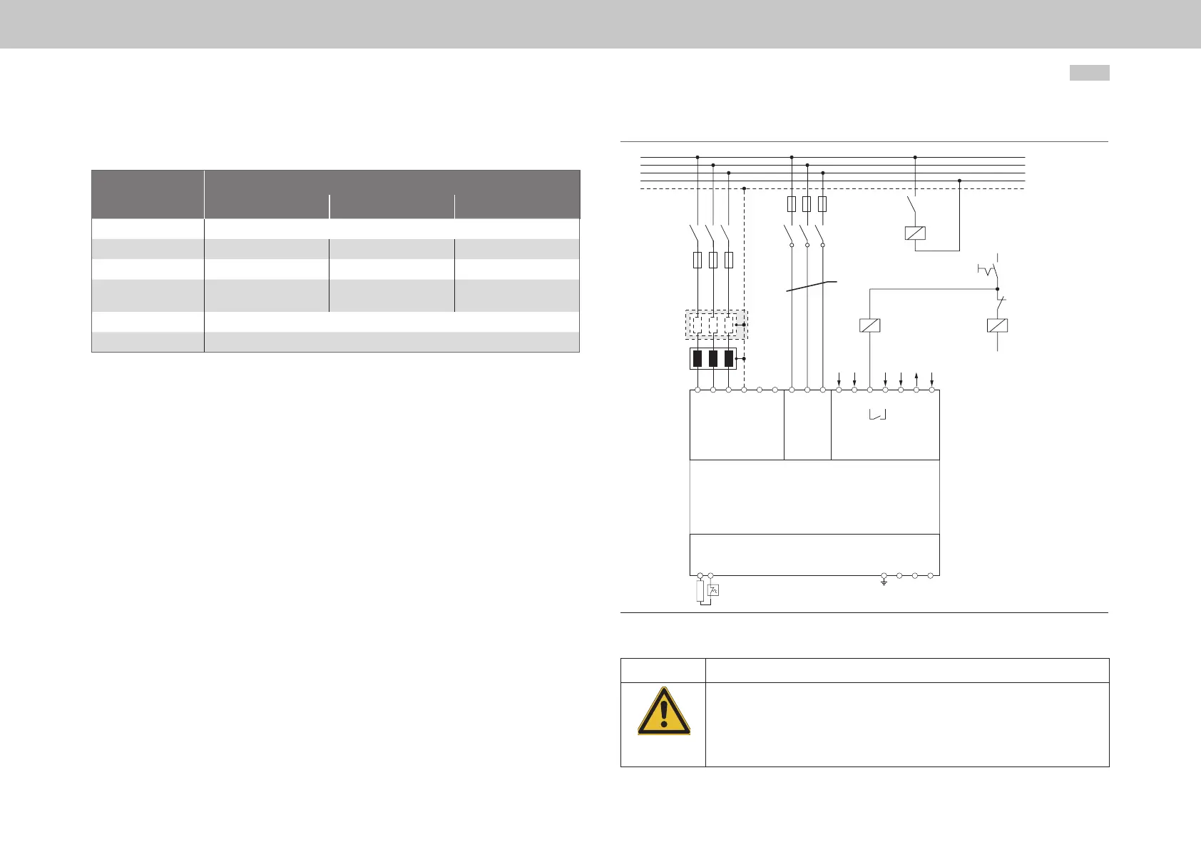
4.8.6 Connection diagram, precharging (only Size 7)
Designation
Specication
G395-250 G395-325 G395-450
Fuses2, slow blow
For values see Table 4.10
Mains lter (optional)
300A 400A
500A
Mains choke (U
k
=2%)
250A 325A
450A
K1 (e.g. Siemens 3RT10 65-
6AP36)
(e.g. Siemens 3RT10 75-
6AP36)
(e.g. Siemens 3RT10
76-6AP36)
K2
12A / 5.5kW / 24V (e.g. Siemens 3RT10 17-1AB01)
K3
7A / 3kW / 24V (e.g. Siemens 3RT10 15-1AB01)
Table 4.9 Example data for Figure 4.17
Wire the precharging circuit according to the standards using short circuit proof cables.
The connection ratings for the internal relay for the terminals X44/3, 4 are
U
max
= 30VDC, I
max
= 6A. Use an auxiliary contactor K3.
Control process
y Precharging the DC link
Switch S1 "Mains supply On" is switched on. The precharging contactor K2 closes and the DC link is
precharged via internal precharging resistors on terminal X45. The main contactor K1 remains open
initially.
y Precharging completed
At a dened DC link voltage the contact on the internal relay on terminal X44/3,4 is closed. The auxiliary
contactor K3 closes and switches on the main contactor K1. The precharging contactor K2 is opened via
an auxiliary contact (normally closed contact) on K1. The MSDServoDrive changes to ready to operate.
y Switching off
Via switch S1 "Mains supply Off" the servo drive is completely disconnected from the mains.
L2
L3
Mains choke
Precharge circuit
short cicuit proof
MainsPrecharge Control
supply
Supply and
triggering of the
motor brake
K2K1
Fuses 1
N
PE
Mains lter
(optional)
Fuses 2
K2
K1
K3
24 V
24 V
S1
GND
GND
GND
24 V
OSD03
GND
G395-250
G305-325
G395-450
internal
relay
RB
− +
L1 L2
L3 PE
WVUPE
ZK- ZK+
X11
L1 L2
L3
X45
X12
Braking
1 2
3 4 5 6 7
X44
K1
K3
Figure 4.17 Connection example, precharging, control/mains supply 3x230/400/460/480V
for Size 7
CAUTION! Shutdown of the precharging!
In order to protect the servo drive against thermal overload, it must be ensured that the
precharging of the DC link is not set for more than 2 minutes without the main contactor
being active. The precharging of the DC link is not designed for high power consumption during
operation.
Failure to do so may destroy the device!