74
MSD Single-Axis System Operation Manual AC-AC Servo Drive
ID no.: CA65642-001 06/2018
moog
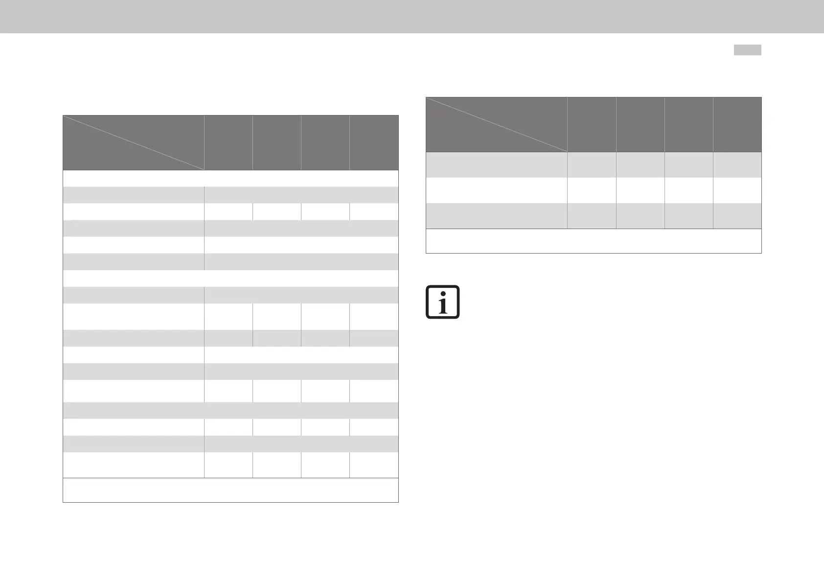
A.2.3 G392-090 to G392-170, air cooling
Designation
Technical data
G392-090
G392-110
G392-143
G392-170
Output, motor side
1)
Voltage
2)
3-phase U
Mains
Rated current, effective (l
n
) 90A 110A 143A 170A
Peak current See A.1.3
Rotating eld frequency 0 ... 400Hz
Switching frequency of the power stage
4, 8, 12, 16kHz
Input, mains side
Mains voltage (3x230V/ 3x400V/ 3x460V/ 3x480V) ±10%
Device connected load
1)
(with mains choke)
62kVA 76kVA 99kVA 118kVA
Current
1)
(with mains choke) 90A 110A 143A 170A
Asymmetry of mains voltage ±3%maximum
Frequency 50/60Hz ±10%
Power dissipation at I
N
1)
1300W 1600W 2100W 2500W
DC link
Capacitance 1060µF 2120µF 3180µF 4240µF
Brake chopper switch-on threshold 820VDC
Minimum ohmic resistance of an externally
installed braking resistor
12Ω 10Ω 8.5Ω 6.5Ω
1) Data referred to mains voltage 3x400V
eff
and switching frequency of the power stage 8kHz
2) When designing the drive, it is to be taken into account that the maximum output voltage reduces as a function of the active power.
Table A.11 Technical data, G392-090 to G392-170, air cooling
Designation
Technical data
G392-090
G392-110
G392-143
G392-170
Brake chopper peak power
with external braking resistor
56kW 67kW 79kW 103kW
Optional:
Internal braking resistor
- - - -
Brake chopper peak power
with internal braking resistor
- - - -
1) Data referred to mains voltage 3x400V
eff
and switching frequency of the power stage 8kHz
2) When designing the drive, it is to be taken into account that the maximum output voltage reduces as a function of the active power.
Table A.11 Technical data, G392-090 to G392-170, air cooling
NOTE:
For more information on the brake chopper and braking resistors also refer to
chapter “4.16 Braking resistor (RB)”