26
Electrical installation
MSD Single-Axis System Operation Manual AC-AC Servo Drive
ID no.: CA65642-001 06/2018
moog
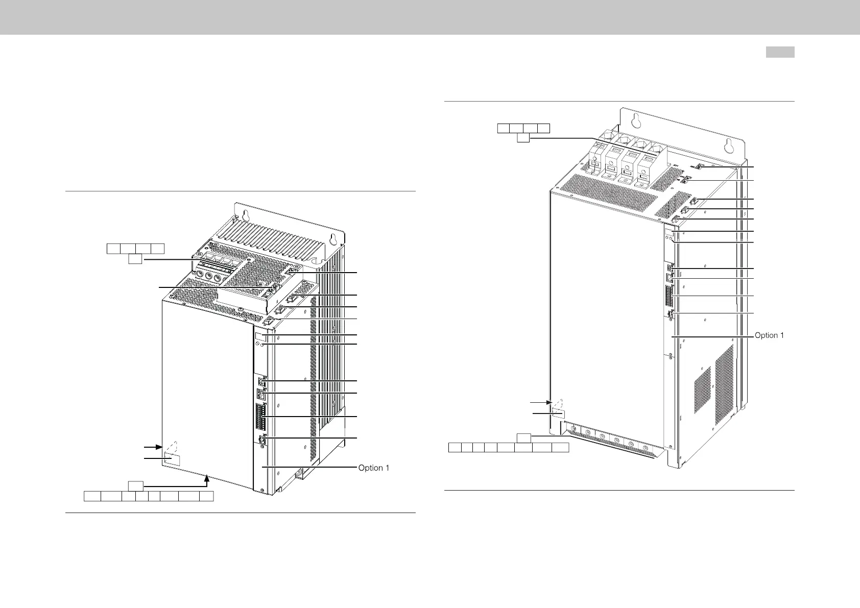
4.4 Overview of the connections, Size 5 to
Size 6A
In the following you will nd the layout with the corresponding positions of the
connectors and terminals. For improved clarity we have added an abbreviation to the
designation for the connectors and terminals.
X20
X8
X7
X6
D1, D2
T1, T2
X2
X3
X4
X5
11
9, X10
SW
HW
12
PE L1 L2 L3
RB- RB+ W V U ZK- ZK+ PE
Figure 4.6 Layout, Size 5 (air cooling housing variant)
X20
X9, X10
X8
X7
X6
D1, D2
T1, T2
X2
X3
X4
X5
11
SW
HW
12
PE L1 L2 L3
PE U V W ZK- ZK+ RB- RB+
Figure 4.7 Layout, Size 6 and Size 6A (Size 6A, liquid cooling housing variant)