MSD Single-Axis System Operation Manual AC-AC Servo Drive
ID no.: CA65642-001 06/2018
moog
29
Electrical installation
4.5.1 Connection diagram
USB 1.1
ISD00
ISD01
ISD02
OSD02
Relay
ENPO (STO)
Motor
3
Option 2
Control
Service
interface
ISDSH (STO)
ISA00+
ISA00-
ISA01+
ISA01-
Analog setpoint 1
Analog setpoint 2
+24 V DC against
DGND
+24 V (U
H
)
3
4
5
6
10
15
16
17
9
23
24
22
RSH
Diagnosis
12
11
1
2
14
13
E/A-GND
Relay
Digital2
RB-
RB+
Braking
resistor
W
V
U
6
8
Triggering of
motor brake
ISD03
ISD04
ISD05
18
19
20
ISD0621
OSD01
8
Digital1
OSD00
7
Digital0
GND
OSD03
+
-
+24 V
5
9
OSD04
54321
10 9876
15 14 13 12 11
DGND
DGND
43 21
9876
~
+
-
D1, D2
T1, T2
Ethernet
L3
PE
L2
L1
L3
L2
L1
ZK+
ZK–
Mains three-phase
Front
Option 1
24 V DC Power supply for
control electronic (U
V
)
Pre-charching: Relay triggering
24 V DC power supply
for brake (I = 2,0 A)
IN
Communication
Field buses
Brake (+)
Brake (-)
(+)
+
–
e.g. additional
encoder
+
–
Encoder
Resolver
1
2
3
4
5
6
7
X11
X2
X3
X4
X44
X8
X7
X6
X5
X12
L3
L2
L1
X45
L3
L2
L1
STO
Service
interface
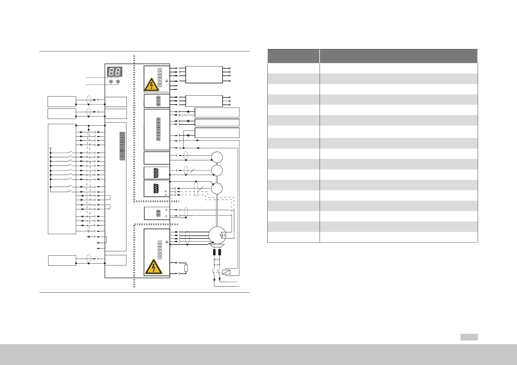
Figure 4.10 Connection diagram, Size 7
Key
No. Designation
D1, D2 7-segment display
T1, T2 Button
X2 USB1.1 interface
X3 Ethernet interface
X4 Control terminals
Option1 Communication
X11
Connection for AC mains supply: 3 x 400/460/480 V G395-250 to G395-450 (Size 7)
and DC link connection
PE Connection for PE conductor
X45 Connection for DC link precharging, see chapter 4.8.6
X44 Connection for control supply, precharging relay and motor brake
X8 (Option2) Technology option
X7 Connection for high-resolution encoder
X6 Connection for resolver
X5 Connection for motor temperature monitoring
X12 Connection for motor phases and braking resistor
HW Hardware rating plate
SW Software rating plate
Table 4.3 Key to connection diagram, Size 7