28
Electrical installation
MSD Single-Axis System Operation Manual AC-AC Servo Drive
ID no.: CA65642-001 06/2018
moog
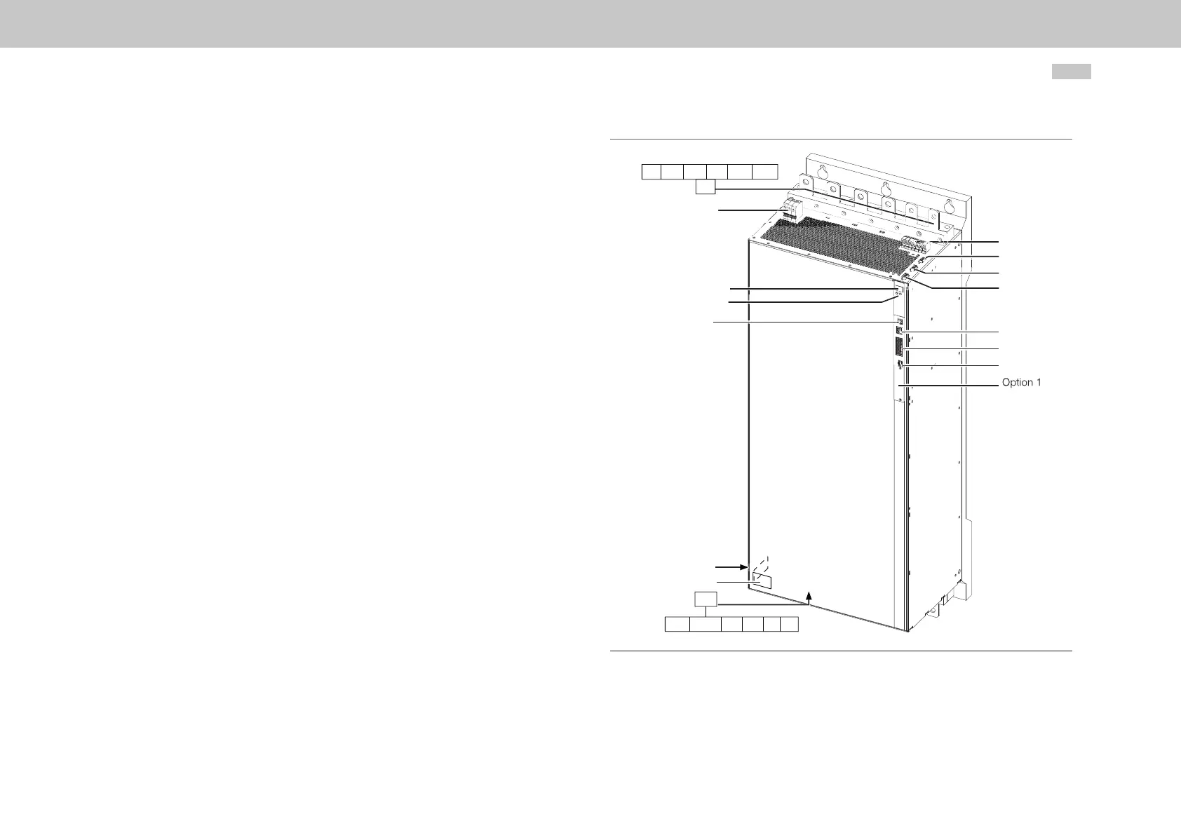
4.5 Overview of the connections, Size 7
The layout on the left shows the corresponding positions of connectors and terminals.
For improved clarity we have added an abbreviation to the designation for the
connectors and terminals.
X11
X45
D1, D2
T1, T2
X2
SW
HW
X12
RB- RB+ PE U V W
L1 L2 L3 PE ZK- ZK+
Figure 4.9 Layout, Size 7 (without shield plates and terminal covers on X11 and X12)