MSD Single-Axis System Operation Manual AC-AC Servo Drive
ID no.: CA65642-001 06/2018
moog
75
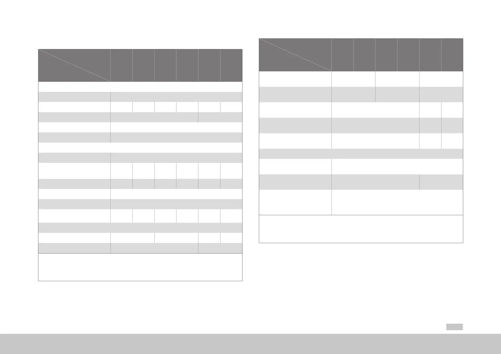
A.2.4 G395-016 to G395-070, liquid cooling
Designation
Technical data
G395-016
G395-020
G395-024
G395-032
G395-053
G395-070
Output, motor side
1)
Voltage
2)
3-phase U
Mains
Rated current, effective (l
n
) 16A 20A 24A 32A 53A 70A
Peak current See A.1.4 See A.1.5
Rotating eld frequency 0 ... 400Hz
Switching frequency of the power stage 4, 8, 12, 16kHz
Input, mains side
Mains voltage (3x230V/ 3x400V/ 3x460V/ 3x480V) ±10%
Device connected load
1)
(with mains choke)
12kVA 15kVA 18.2kVA 24.2kVA 36.7kVA 48.5kVA
Current
1)
(with mains choke)
17.3A 21.6A 26.2A 34.9A 53A 70A
Asymmetry of mains voltage ±3%maximum
Frequency 50/60Hz ±10%
Power dissipation at I
N
1)
330W 400W 475W 515W 690W 930W
DC link
Capacitance 1230µF 2000µF 430µF 900µF
Brake chopper switch-on threshold 650VDC
1)
820VDC
1) Data referred to mains voltage 3x400V
eff
and switching frequency of the power stage 8kHz
2) When designing the drive, it is to be taken into account that the maximum output voltage reduces as a function of the active power.
3) Connection of an ext. braking resistor to devices with int. braking resistor not permitted (model G395-xxx-xxx-xx2/xx4)!
4) Cooling performance adequate also with optional internal braking resistor
Table A.12 Technical data, G395-016 to G395-070, liquid cooling
Designation
Technical data
G395-016
G395-020
G395-024
G395-032
G395-053
G395-070
Minimum ohmic resistance of an
externally installed braking resistor
20Ω 12Ω 10Ω
3)
Brake chopper peak power with external
braking resistor
21kW 35kW 67kW
Optional:
Internal braking resistor
- 20Ω 10Ω
Brake chopper continuous power
with internal braking resistor
- 675W 1350W
Brake chopper peak power
with internal braking resistor
- 34kW 67kW
Chiller data
Coolant pressure
(rated value / maximum value)
1 / 2bar
Coolant ow rate
4)
(rated value / maximum value)
3 / 4l per min 8 / 11l per min
Feed coolant temperature
The coolant temperature can be between +5 °C (+41 °F) and +40°C
(+104 °F). However, the coolant temperature should not be more than
10°K below the ambient temperature to prevent condensation on the heat
sink.
1) Data referred to mains voltage 3x400V
eff
and switching frequency of the power stage 8kHz
2) When designing the drive, it is to be taken into account that the maximum output voltage reduces as a function of the active power.
3) Connection of an ext. braking resistor to devices with int. braking resistor not permitted (model G395-xxx-xxx-xx2/xx4)!
4) Cooling performance adequate also with optional internal braking resistor
Table A.12 Technical data, G395-016 to G395-070, liquid cooling