MSD Single-Axis System Operation Manual AC-AC Servo Drive
ID no.: CA65642-001 06/2018
moog
41
Electrical installation
4.14.3 Ready made encoder cables
The specications can only be assured on the usage of Moog system cables.
C08335 - 013 - yyy
Encoder cable
Ready made cable
Resolver cable
Encoder cable SSI, EnDat CA58876
Encoder cable Hiperface® CA58877
002
002
Encoder system
Version
Cable length (m)
1) yyy stands for length in meters; standard length: 1 m (3.28 ft), 5 m (16.40 ft), 10 m (32.80 ft), 15 m (49 ft), 20 m (65 ft),
50 m (164 ft). Further length on request
Encoder cable C08335-013-yyy
1)
Order code
CO8335-013-yyy
1)
CA58876-002-yyy
1)
CA58877-002-yyy
1)
Motors with encoder system Resolver
G3, G5, G12.x
(singleturn / multiturn
encoder with SSI/EnDat
interface)
G6, G6.x
(singleturn / multiturn
encoder with
HIPERFACE
®
interface)
Drive-end assignment
(Sub-D connector)
1 = S3
2 = S1
3 = S2
4 = n.c.
5 = PTC+
6 = R1
7 = R2
8 = S4
9 = PTC-
1 = A-
2 = A+
3 = VCC (+5V)
4 = DATA+
5 = DATA-
6 = B-
8 = GND
11 = B+
12 = VCC (Sense)
13 = GND (Sense)
14 = CLK+
15 = CLK-
7, 9, 10 = n.c.
1 = REFCOS
2 = +COS
3 = U
S
7 – 12V
4 = Data + RS485
5 = Data- RS485
6 = REFSIN
7 = Jumper to pin12
8 = GND
11 = +SIN
12 = Jumper to pin7
9, 10, 13, 14, 15 = n.c.
Capable for energy chains Yes
Minimum bending radius 90 mm (3.54 in) 100 mm (3.93 in) 90 mm (3.54 in)
Temperature range
-40 to +85 °C
(-40 to +185 °F)
-35 to +80 °C
(-31 to +176 °F)
-40 to +85 °C
(-40 to +185 °F)
Table 4.15 Technical data, encoder cables
CO8335-013-yyy
1)
CA58876-002-yyy
1)
CA58877-002-yyy
1)
Cable diameter approx. 8.8 mm (0.34 in)
Outer sheath material PUR
Resistance Oil, hydrolysis and microbe resistant (VDE0472)
Approvals
UL style 20233, +80 °C (+176 °F) - 300V,
CSA-C22.2N.210-M90, +75 °C (+167 °F) - 300V FT1
Table 4.15 Technical data, encoder cables
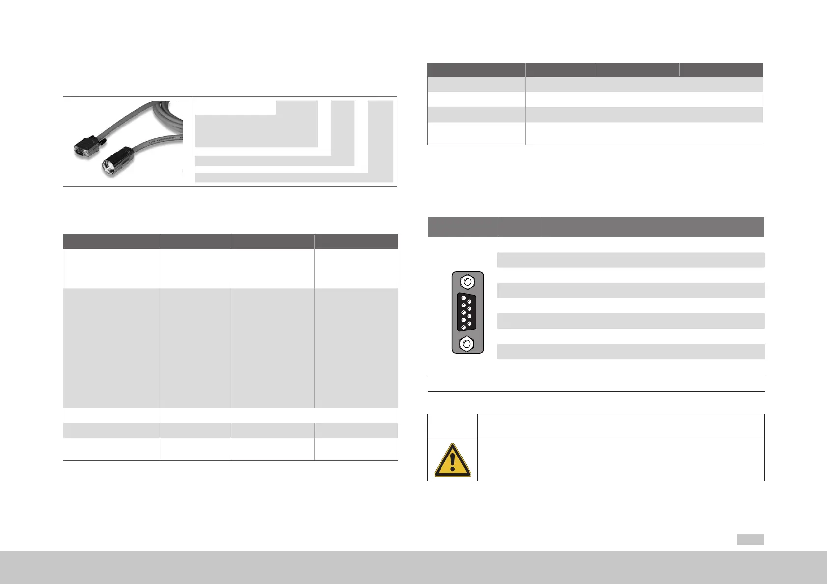
4.14.4 Resolver connection
A resolver is connected to slot X6 (9-pin D-Sub socket).
Fig. X6/pin Function
5 4 3 2 1
9 8 7 6
X6
Resolver
1 Resolver S3 differential input (reference to Pin X6-2)
2 Resolver S1 differential input (reference to Pin X6-1)
3 Resolver S2 differnetial input (reference to Pin X6-8)
4 Supply voltage 5..12V, connected internally to X7/3
5
ϑ+ (PTC, NTC, KTY, Klixon) 1)
6 Ref+ analog excitation
7 Ref- analog excitation (ground reference point to pin6)
8 Resolver S4 differntial input (reference to Pin X6-3)
9
ϑ- (PTC, NTC, KTY, Klixon)
1)
1) It is imperative attention is paid to the warning
Table 4.16 Pin assignment X6
CAUTION
Damage to the device due to incorrect insulation of the motor
winding!
• Carelessness can cause damage to the motor/device
The motor temperature sensor must, in relation to the motor winding, on connection to X5 be
provided with basic insulation, on connection to X6 or X7 with reinforced insulation
as per IEC/EN61800-5-1.