38
Electrical installation
MSD Single-Axis System Operation Manual AC-AC Servo Drive
ID no.: CA65642-001 06/2018
moog
Des. Term. Specication Electrical isolation
Digital outputs
REL
REL
ISDSH
ISD06
ISD05
ISD04
ISD03
ISD02
ISD01
ISD00
+24V
DGND
RSH
RSH
ENPO
OSD02
OSD01
OSD00
ISA1-
ISA1+
ISA0-
ISA0+
+24V
DGND
24
23
22
21
20
19
18
17
16
15
14
13
12
11
10
9
8
7
6
5
4
3
2
1
OSD00
OSD01
OSD02
X4/7
X4/8
X4/9
• No irreparable damage in the event of a short circuit
(+24V -> GND), however, device may briey shut down.
• I
max
= 50mA, PLC-compatible
• Terminal scan cycle in =1ms
• High-side driver
Yes
STO "Safe Torque Off" (*)
ISDSH
(STO)
X4/22
• Input "Request STO" = low level
• OSSD support (from hardware version 2)
• Switching level low/high: ≤4.8V / ≥18V
• U
IN max
= +24VDC +20%
• I
IN
at +24VDC = typ. 3mA
Yes
RSH
RSH
X4/11
X4/12
Diagnostics STO, both shut-off channels
active, one NO contact with automatically
resetting circuit breaker (polyswitch)
• 25V/200mAAC, cosϕ=1
• 30V/200mADC, cosϕ=1
Yes
Relay output
REL
X4/23
X4/24
Relay, 1 NO contact
• 25V/1.0AAC, cosϕ=1
• 30V/1.0ADC, cosϕ=1
• Switching delay approx.10ms
• Cycle time 1ms
X4/24
Auxiliary voltage
+24 V
X4/2
X4/14
• Auxiliary voltage for supplying the digital inputs
• U
H
=U
V
-∆U (∆U typically approx. 1.2V), no irreparable
damage in the event of a short circuit (+24V -> GND), but
device may briey shut down.
• I
max
= 80mA (per pin) with self-resetting circuit breaker
(polyswitch)
Yes
Digital ground
DGND
X4/1
X4/13
Reference ground for 24V, I
max
=80mA (per pin), hardware
versions 0..1 with self-resetting circuit breaker (polyswitch)
Yes
(*) STO certication only applies for Size 1 to Size 6A
Table 4.10 Specication of the control connections X4
NOTE:
If excessively high currents ow via the earth terminals, high-impedance
isolation from the device ground is possible. In some circumstances this can
result in the malfunction of the drive. To prevent this situation arising, avoid
currents circulating in the wiring.
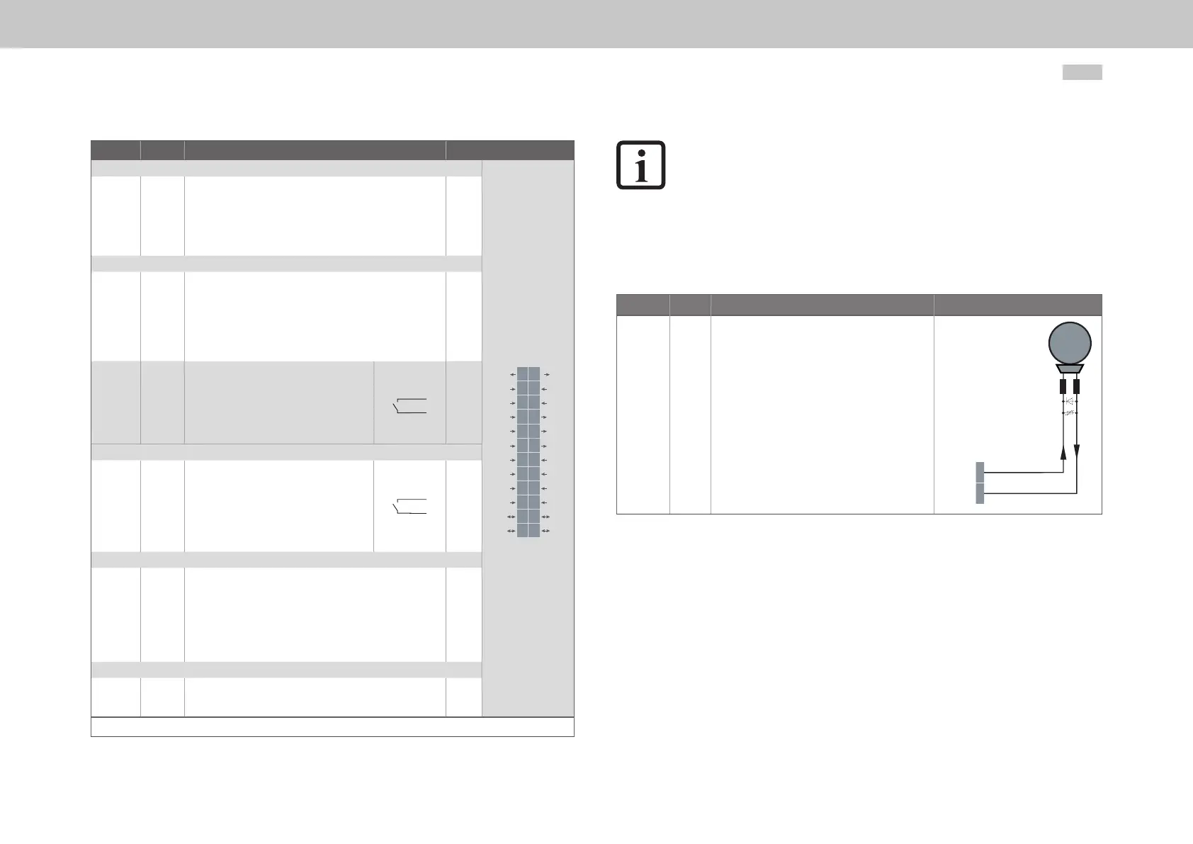
4.9.2 Brake driver
On Size 1 to Size 4 the connector X13 is intended to be used to connect a motor brake.
Des. Term. Specication Connection
OSD03
GND
X13/1
X13/2
• Short circuit proof
• Power is supplied via the control supply U
V
on
X9/X10.
• U
BR
=U
V
-∆U` (∆U` typically approx.1.4V)
• For operating a motor holding brake up to
I
BR
=2.0Amaximum, for brakes with a higher
current requirement a relay must be connected
in between.
• Overcurrent causes shutdown
• Can also be used as congurable digital output.
• Congurablecablebreakmonitoring<500mA
in state "1" (up to the relay)
X13
M
Brake (+)
Brake (-)
1
GND 2
Table 4.11 Specication of the terminal connections X13 (Size 1 to Size 4)
On Size 5 to Size 6A the connector X20 is intended to be used to connect a motor
brake.