MSD Single-Axis System Operation Manual AC-AC Servo Drive
ID no.: CA65642-001 06/2018
moog
73
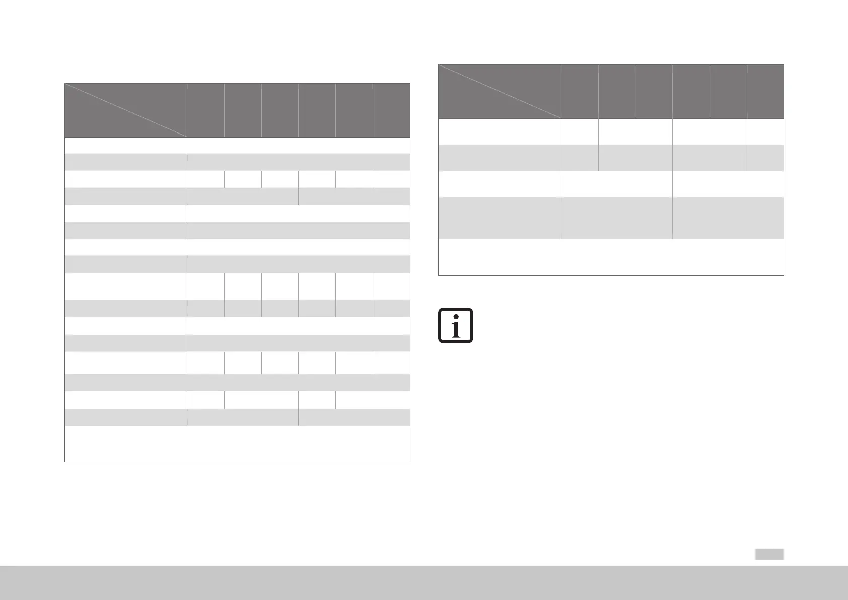
A.2.2 G392-020 to G392-072, air cooling
Designation
Technical data
G392-020
G392-024
G392-032
G392-045
G392-060
G392-072
Output, motor side
1)
Voltage
2)
3-phase U
Mains
Rated current, effective (l
n
) 20A 24A 32A 45A 60A 72 A
Peak current See A.1.2 See A.1.3
Rotating eld frequency 0 ... 400Hz
Switching frequency of the power stage
4, 8, 12, 16kHz
Input, mains side
Mains voltage (3x230V/ 3x400V/ 3x460V/ 3x480V) ±10%
Device connected load
1)
(with mains choke)
15kVA 18.2kVA 24.2kVA 31.2kVA 41.0kVA 50kVA
Current
1)
(with mains choke) 21.6A 26.2A 34.9A 45A 60A 72A
Asymmetry of mains voltage ±3%maximum
Frequency 50/60Hz ±10%
Power dissipation at I
N
1)
400W 475W 515W 610W 830W 1010W
DC link
Capacitance 1230µF 2000µF 430µF 900µF
Brake chopper switch-on threshold 650VDC
1)
820VDC
1) Data referred to mains voltage 3x400V
eff
and switching frequency of the power stage 8kHz
2) When designing the drive, it is to be taken into account that the maximum output voltage reduces as a function of the active power.
3) Connection of an ext. braking resistor to devices with int. braking resistor not permitted (model G392-xxx-xxx-xx2/xx4)!
Table A.10 Technical data, G392-020 to G392-072, air cooling
Designation
Technical data
G392-020
G392-024
G392-032
G392-045
G392-060
G392-072
Minimum ohmic resistance of an
externally installed braking resistor
20Ω
3)
12Ω
3)
18Ω 13Ω
Brake chopper peak power
with external braking resistor
21kW
1)
35kW
1)
37kW 52kW
Optional:
Internal braking resistor
90Ω
-
Brake chopper peak power
with internal braking resistor
See “Table 4.21 Data on the
integrated braking resistor (model
G392-xxx-xxx-xx2/xx4 and G395-
xxx-xxx-xx2/xx4)”
-
1) Data referred to mains voltage 3x400V
eff
and switching frequency of the power stage 8kHz
2) When designing the drive, it is to be taken into account that the maximum output voltage reduces as a function of the active power.
3) Connection of an ext. braking resistor to devices with int. braking resistor not permitted (model G392-xxx-xxx-xx2/xx4)!
Table A.10 Technical data, G392-020 to G392-072, air cooling
NOTE:
For more information on the brake chopper also refer to chapter “4.16 Braking
resistor (RB)”