MSD Single-Axis System Operation Manual AC-AC Servo Drive
ID no.: CA65642-001 06/2018
moog
37
Electrical installation
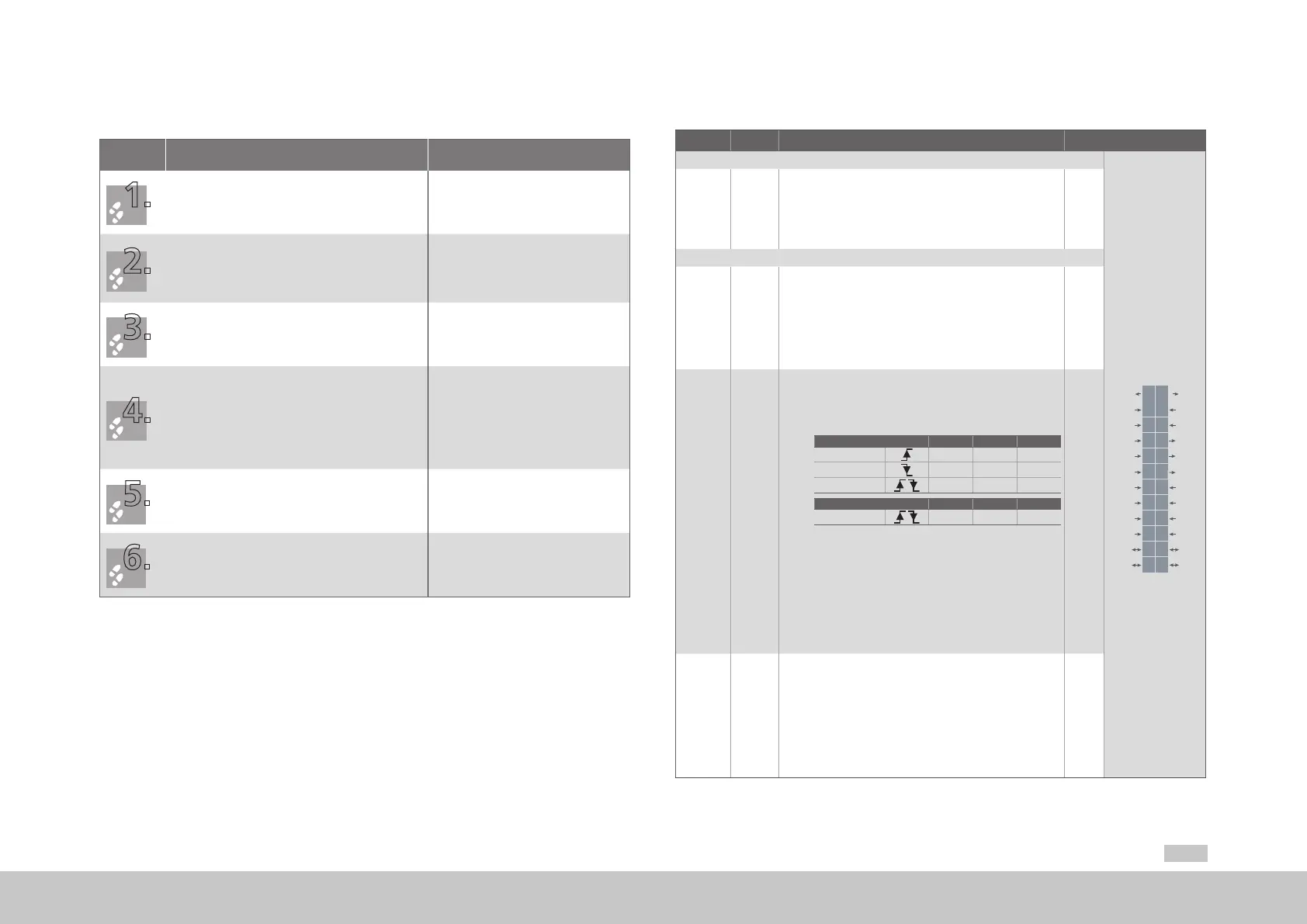
4.9 Control connections
Step Action Comment
Check whether a complete device setup is already
available, i.e. whether the drive has already been
congured.
If so, a special control terminal assignment applies.
Please contact your project engineer to obtain the
terminal assignment!
Choose a
terminal assignment.
Wire the control terminals using
shielded cables.
The following are imperative:
ISDSH (X4/22) and ENPO (X4/10)
Ground the cable shields over a
large area at both ends.
Cable cross-sections: 0.2 to 1.5 mm²
(0.0003 to 0.002 in²),
with ferrules with plastic sleeve
maximum0.75mm² (0.001 in²)
Keep all contacts open
(inputs inactive).
Check all connections again!
4.9.1 Specication of the control connections
Des. Term. Specication Electrical isolation
Analog inputs
REL
REL
ISDSH
ISD06
ISD05
ISD04
ISD03
ISD02
ISD01
ISD00
+24V
DGND
RSH
RSH
ENPO
OSD02
OSD01
OSD00
ISA1-
ISA1+
ISA0-
ISA0+
+24V
DGND
24
23
22
21
20
19
18
17
16
15
14
13
12
11
10
9
8
7
6
5
4
3
2
1
ISA0+
ISA0-
ISA1+
ISA1-
X4/3
X4/4
X4/5
X4/6
• U
IN
=±10VDC
• Resolution 12bits; R
IN
approx.101kΩ
• Terminal scan cycle in the "IP mode" 125µs, otherwise
1ms
• Tolerance: U±1% of the measuring range end value
No
Digital inputs
ISD00
ISD01
ISD02
ISD03
ISD04
X4/15
X4/16
X4/17
X4/18
X4/19
Standard input
• U
IN max
= +24VDC +20%
• I
max
at24V = 3mA typ.
• Switching level low/high: ≤4.8V/≥18V
• Frequencyrange<500Hz
• Sampling cycle: 1ms
Yes
ISD05
ISD06
X4/20
X4/21
Touchprobe or standard input
• Input for touchprobe for quickly saving process data
(e.g.actual position)
− Internal signal delay
Hardware version 0..1 Min. Max. Typ.
ISD05 3µs 16µs 8µs
ISD05 4µs 27µs 15µs
ISD06
2µs
From hardware version 2 Min. Max. Typ.
ISD05 + ISD06
2µs
− Activation via ISD05/ISD06 = 15(PROBE)
• Standard input
− Frequency range ≤500Hz
− Sampling cycle: 1ms
• U
IN max
= +24VDC +20%
• I
IN max
at+24VDC =10mA, R
IN
=approx. 3kΩ
• Switching level low/high: ≤4.8V/≥18V
Yes
ENPO X4/10
• Disable restart inhibit (STO) and enable power stage =
High level
• OSSD support (from hardware version 2)
• Response time approx. 10ms
• Switching level low/high: ≤4.8V / ≥18V
• U
IN max
= +24VDC +20%
• I
IN
at +24VDC = typ. 3mA
Yes
Table 4.10 Specication of the control connections X4