46
Electrical installation
MSD Single-Axis System Operation Manual AC-AC Servo Drive
ID no.: CA65642-001 06/2018
moog
4.16.2 Model with integrated braking resistor Size 1 to Size 4
For the servo drives with an integrated braking resistor (model G392-xxx-xxx-xx2/xx4
and G395-xxx-xxx-xx2/xx4, only available up to and including Size 4) only the peak
braking power is stated in the catalog. The permissible continuous braking power must
be calculated. It depends on the effective utilisation of the drive in the corresponding
application.
CAUTION!
Damage to the device with integrated braking resistor due to
connection of an external braking resistor!
• Carelessness can cause damage to the device
No additional external braking resistor may be connected to servo drives G392-008 to
G392-032/G395-032 with integrated braking resistor.
The servo drive is thermally designed in such a way that no energy input by the internal
braking resistor is permitted during continuous operation at rated current and at
maximum ambient temperature.
Consequently, a drive design featuring an integrated braking resistor only makes sense
when the effective servo drive load is ≤80% or the braking resistor is designed for one-
off emergency stop. In the event of an emergency stop, only the thermal capacity of the
braking resistor can be used for a one-off braking action. The permissible energy WIBr
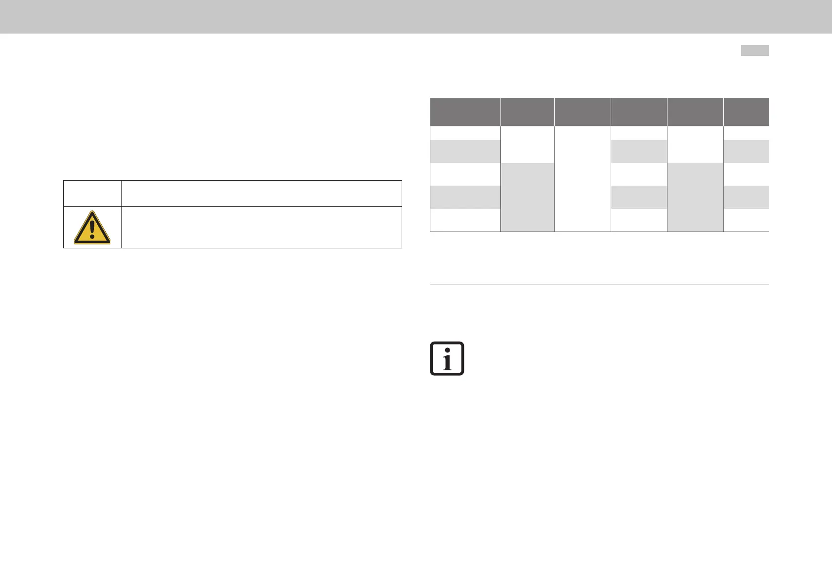
can be taken from the following table.
Device Technology
Rated
resistance R
BR
Peak braking
power P
PBr
Pulse
energy W
IBr
K1
G392-004A
PTC
90Ω
1690W
1)
600Ws
95W
G392-004
G392-006
1690W
2)
95W
G392-008
G392-012
Wire resistance
4700W
3)
6000Ws
230W
G392-016/G395-016
G392-020/G395-020
6170W
4)
360W
G392-024/G395-024
G392-032/G395-032
6500W
5)
480W
1) Data referred to 1x230V mains voltage (BR switch-on threshold 390V
DC
)
2) Data referred to 3x230V mains voltage (BR switch-on threshold 390V
DC
)
3) Data referred to 3x400V mains voltage (BR switch-on threshold 650V
DC
)
4) Data referred to 3x460V mains voltage (BR switch-on threshold 745V
DC
)
5) Data referred to 3x480V mains voltage (BR switch-on threshold 765V
DC
)
Table 4.21 Data on the integrated braking resistor (model G392-xxx-xxx-xx2/xx4 and G395-xxx-xxx-xx2/xx4)
If the drive is not permanently operated at its power limit, the reduced power dissipation
of the drive can be used as braking power.
NOTE:
The rest of the calculation assumes that the servo drive is used at maximum
permissible ambient temperature. This means that any additional energy input
from the internal braking resistor caused by low ambient temperature will be
neglected.
4.16.3 Model with integrated braking resistor Size 5 to Size 7
Servo drives of sizes 5 to 7 with liquid cooling can be equipped with an integrated
braking resistor as an option. You will nd the technical data in chapter A.2