42
Electrical installation
MSD Single-Axis System Operation Manual AC-AC Servo Drive
ID no.: CA65642-001 06/2018
moog
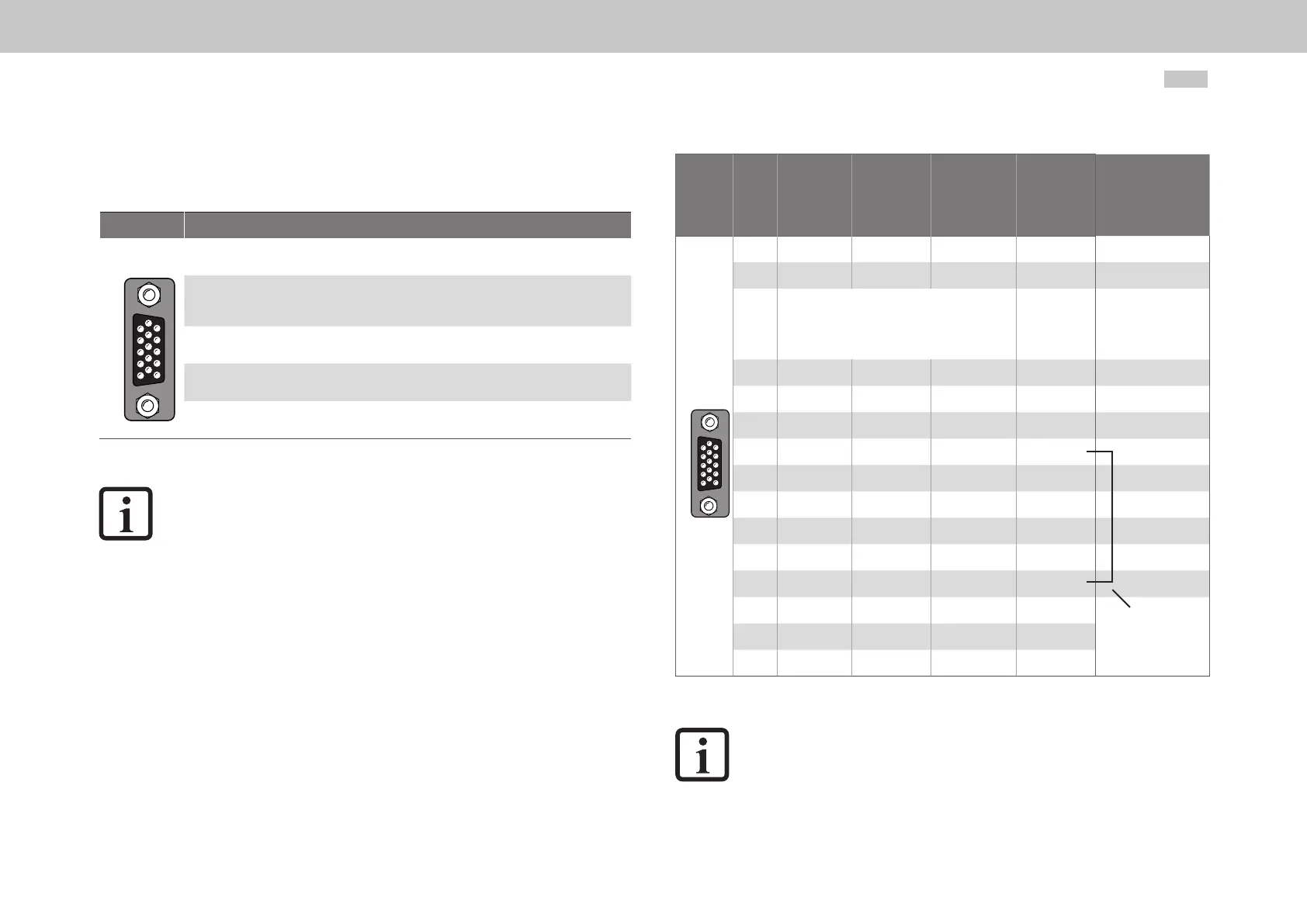
4.14.5 Connection for high-resolution encoders
The interface X7 makes it possible to evaluate the following encoder types.
Fig. Function
54321
10 9876
15 14 13 12 11
Sin/Cos encoder with zero pulse
e.g. Heidenhain ERN1381, ROD486
Heidenhain Sin/Cos encoder with fully digital EnDat interface
e.g. 13-bit singleturn encoder (ECN1313.EnDat01) and 25-bit multiturn encoder
(EQN1325-EnDat01)
Heidenhain encoder with digital EnDat interface
Single or multiturn encoder
Sin/Cos encoder with SSI interface
e.g. 13-bit singleturn and 25-bit multiturn encoder (ECN413-SSI, EQN425-SSI)
Sick-Stegmann Sin/Cos encoder with HIPERFACE® interface
Single and multiturn encoder, e.g. SRS50, SRM50
Table 4.17 Suitable encoder types on X7
NOTE:
The usage of encoders not included in the range supplied by Moog requires
special approval by Moog.
y The maximum signal input frequency is 500kHz.
y Encoders with a power supply of 5V ±5% must have a separate sensor
cable connection. The sensor cable detects the actual supply voltage at
the encoder; it is then possible to compensate for the voltage drop on
the cable. Only by using the sensor cable is it ensured that the encoder
is supplied with the correct voltage. The sensor cable must always be
connected.
Select the cable type specied by the motor or encoder manufacturer. During this
process bear in mind the following boundary conditions:
y Always used shielded cables. Connect the shield at both ends.
y Connect the differential track signals A/B, R or CLK, DATA using twisted pairs.
y Do not cut the encoder cable, for example to route the signals via terminals in the switch cabinet.
Fig.
X7
pin
SinCos
and TTL
SinCos
absolute
value
encoder
SSI/EnDat
Absolute value
encoder EnDat
(digital)
Absolute
value
encoder
HIPERFACE®
Comment
54321
10 9876
15 14 13 12 11
1 A- A- - REFCOS
2 A+ A+ - +COS
3
+5VDC ±5%, IOUT maximum =250mA (150mA
for hardware versions 0..1), monitoring via sensor
cable
7 to 12V
(typ. 11V)
maximum
100mA
The sum of the currents
tapped at X7/3 and X6/4
must not exceed the
specied value!
4 - Data + Data + Data +
5 - Data - Data - Data -
6 B- B- - REFSIN
7 - - - U
S
- switch
8 GND GND GND GND
9 R- - - -
10 R+ - - -
11 B+ B+ - +SIN
12 Sense + Sense + Sense + U
S
- switch
13 Sense - Sense - Sense - -
After connecting pin 7
to pin 12, a voltage of
11.8V is set on X7,
pin3!
14 - CLK+ CLK+ -
15 - CLK - CLK - -
Table 4.18 Pin assignment for the connector X7
NOTE:
The encoder supply at X7/3 is short circuit proof on both 5V and 11V
operation. The drive remains in operation enabling the generation of a
corresponding error message on evaluating the encoder signals.