MTR3000 Backplane: Description 6-15
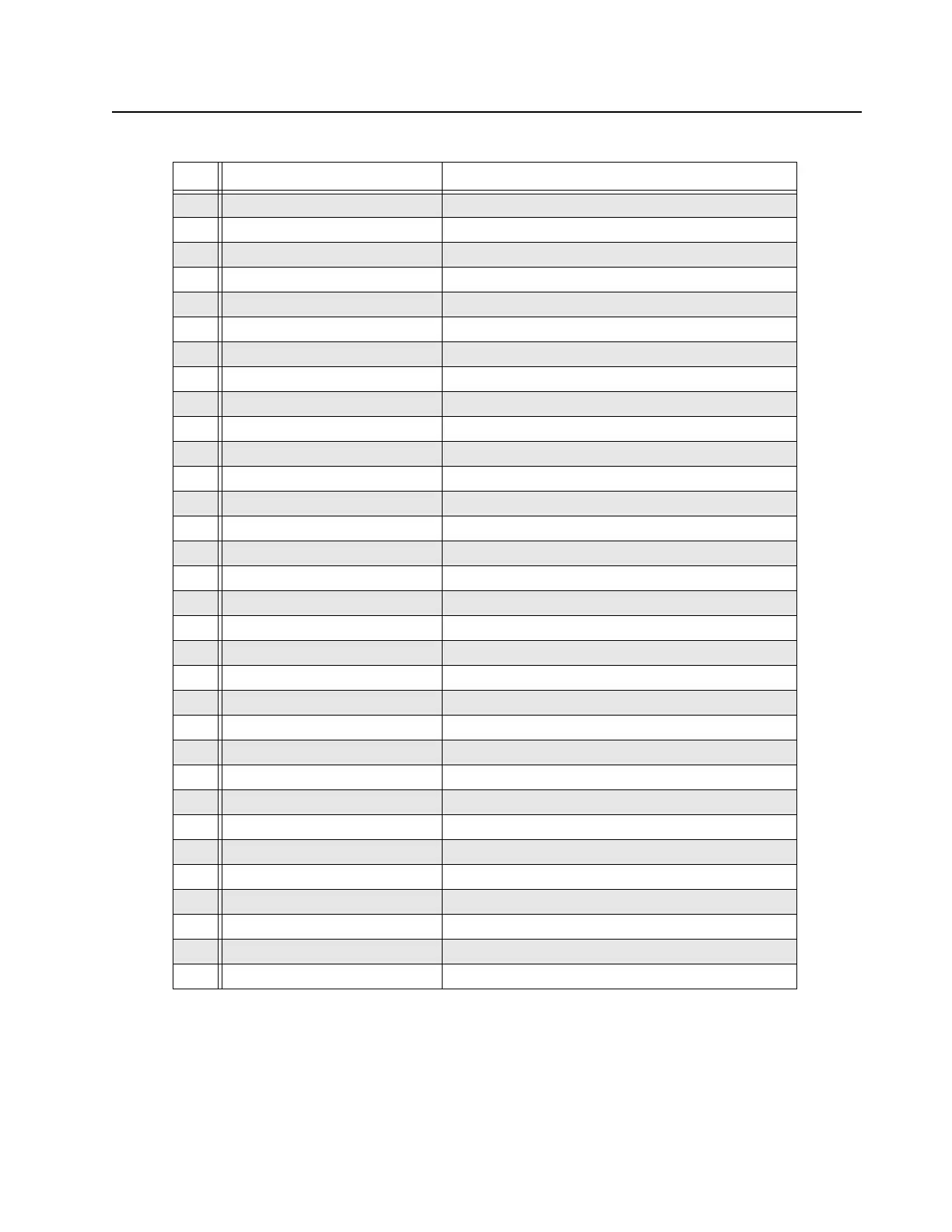
Table 6-10 J3 Controller Connector, Row B Pins
Pin # Pin Assignment To/From
1 14.2 VDC P8 pins 3, 4 (through F1)
2 GND Station ground
3 5VDC P8 pins 7, 8
4 Wireline 3/4 TXD J4-B4
5 Wireline 1/2 RXD J4-B5
6 Wireline MCLK J4-A1
7 Wireline2 Latch CS* J4-B6
8 MISO P7-9, J1-B8, J2-B8, J4-B8
9 N/C N/C
10 N/C N/C
11 OP1 CS1* J1-B11
12 OP2 CS1* J2-B11
13 PA D/A CS* P7-6
14 10 VDC Regulator U101-3
15 10 VDC Regulator U101-3
16 Reset* J1-B16, J2-B16, J4-B16, P7-3
17 N/C N/C
18 Option2 ID J2-C19
19 Reserved –
20 Reserved J1-B20, J2-B20, J4-B20
21 N/C N/C
22 GND Station ground
23 N/C N/C
24 Carrier Detect Switch J1-B29, J2-B29, J5-B4
25 Reserved –
26 Reserved –
27 Reserved J4-B13
28 GND Station ground
29 Tx_Data_PL_DPL J7-13
30 Tx Audio J7-1
31 GPIO_3 J7-15, J4-A18
32 GPIO_2 J7-4, J4-C18
 Loading...


