MTR3000 Power Supply: Basic Troubleshooting 7-7
7.4 Basic Troubleshooting
7.4.1 Replacement Procedure
For procedure to replace the Power Supply module, refer to Section 14.7.2.3 on page 14-8.
7.4.2 Basic Voltage Check Procedure
This section is to illustrate measurement of the 28.6 VDC, 14.2 VDC, and 5.1 VDC sources if a
known good AC or DC source is applied to the Power Supply but there is no apparent activity from
the base station/repeater.
To check the basic voltage for base station/repeater failure, such as no power indicated to the base
station/repeater when the AC and DC mains are connected, perform the following steps:
1. Turn on the base station/repeater power at source (e.g. AC or DC breaker).
2. Push a voltmeter probe into the power connector at the backplane interface board or PA
adjacent to the indicated wires. Ensure enough of the probe tip is inserted to touch the metal
Pin inside the connector housing.
3. Touch the other voltmeter probe anywhere on the chassis (or either casting) to complete the
measurement circuit.
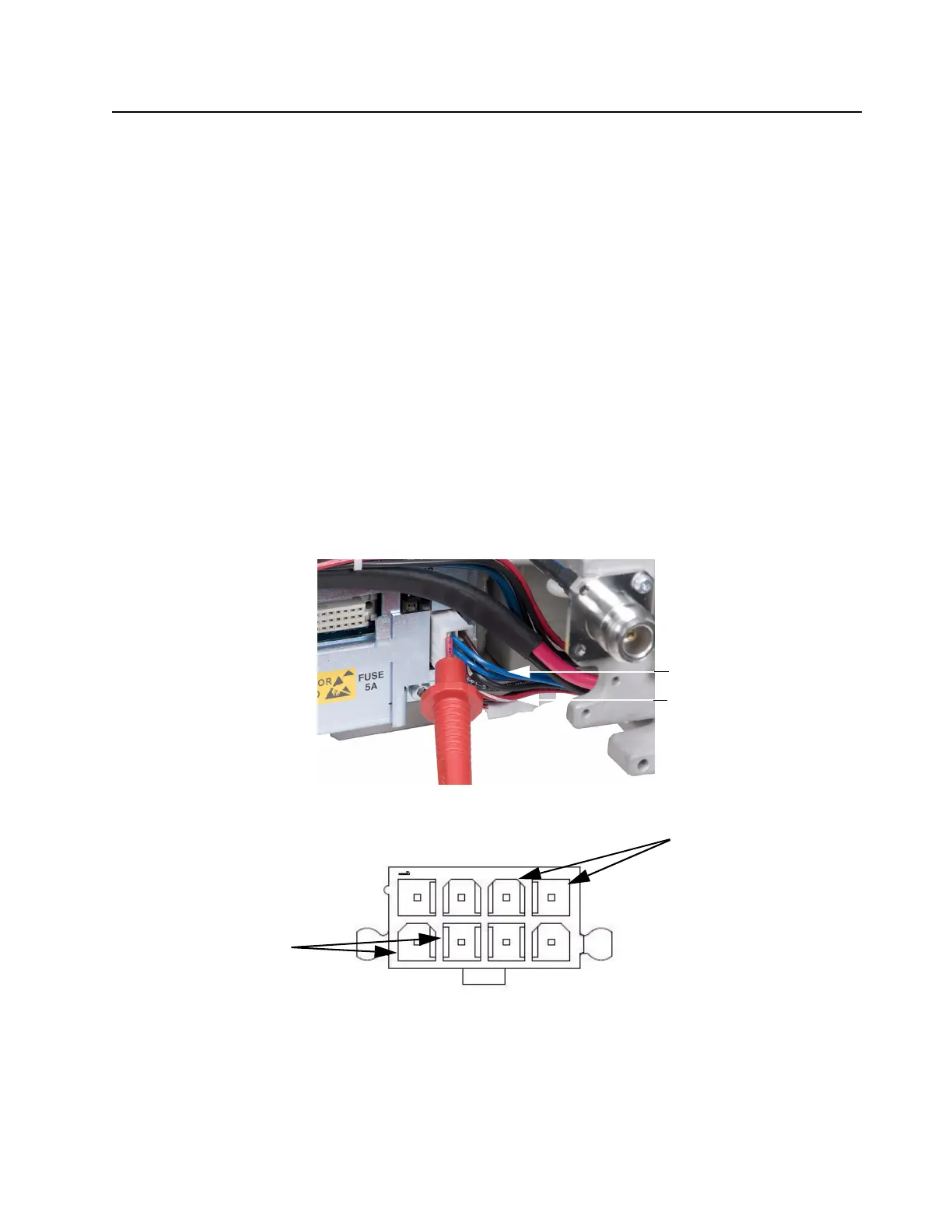
To measure the 14.2 VDC and 5.1 VDC, refer to Figure 7-3. For the pin-out, refer to Figure 7-4.
Figure 7-3 Measuring 14.2 VDC and 5.1 VDC (other voltmeter probe to chassis)
Figure 7-4 Pin-out of connector (measuring 14.2 VDC and 5.1 VDC)
1
4
1
4
5
8
14.2VDC (either blue wire)
5.1VDC (either red-white wire)
14.2 VDC (blue wires)
5.1 VDC (red-white wires)
 Loading...


