7-8 MTR3000 Power Supply: Basic Troubleshooting
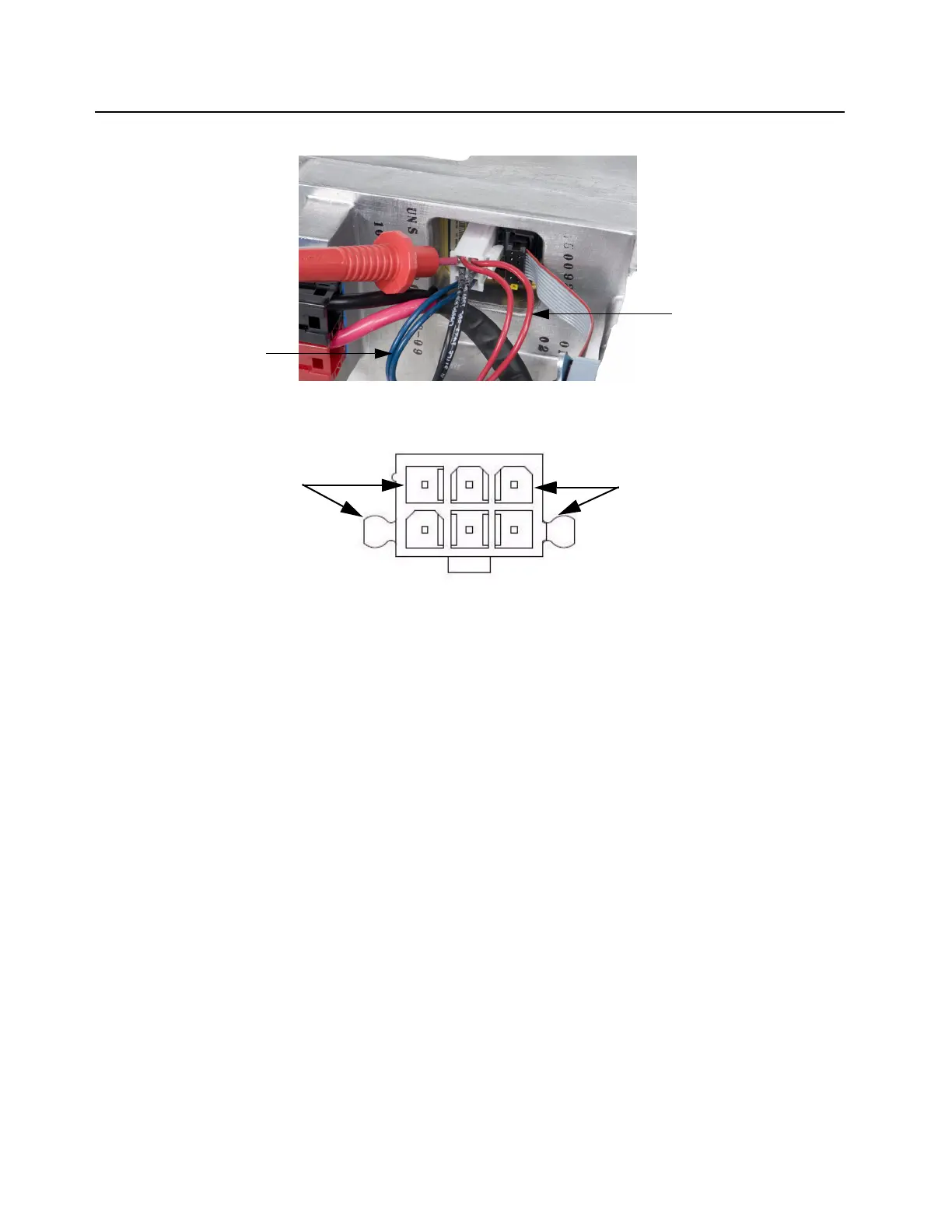
To measure the 14.2 VDC and 28.6 VDC, refer to Figure 7-5 For the pin-out, refer to Figure 7-6
Figure 7-5 Measuring 14.2 VDC and 28.6 VDC (other voltmeter probe to chassis)
Figure 7-6 Pin-out of connector (measuring 14.2 VDC and 28.6 VDC)
1
4
3
6
28.6 VDC (either red wire)
14.2 VDC (either blue wire)
14.2 VDC (blue wires)
28.6 VDC (red wires)
 Loading...


