8-6 MTR3000 Wireline: Functional Theory Of Operation
8.3.2 Board Configuration
There is only one option on the Wireline board that must be configured through jumpers. All other
configuration settings are modified using the Customer Programming Software (CPS).
8.3.2.1 Jumper Configuration
When operating the Wireline board in DC Remote Control mode, the jumpers on header P8 must be
set. These jumpers route DC Control currents from the correct Wireline pair to the DC Remote
Decoder.
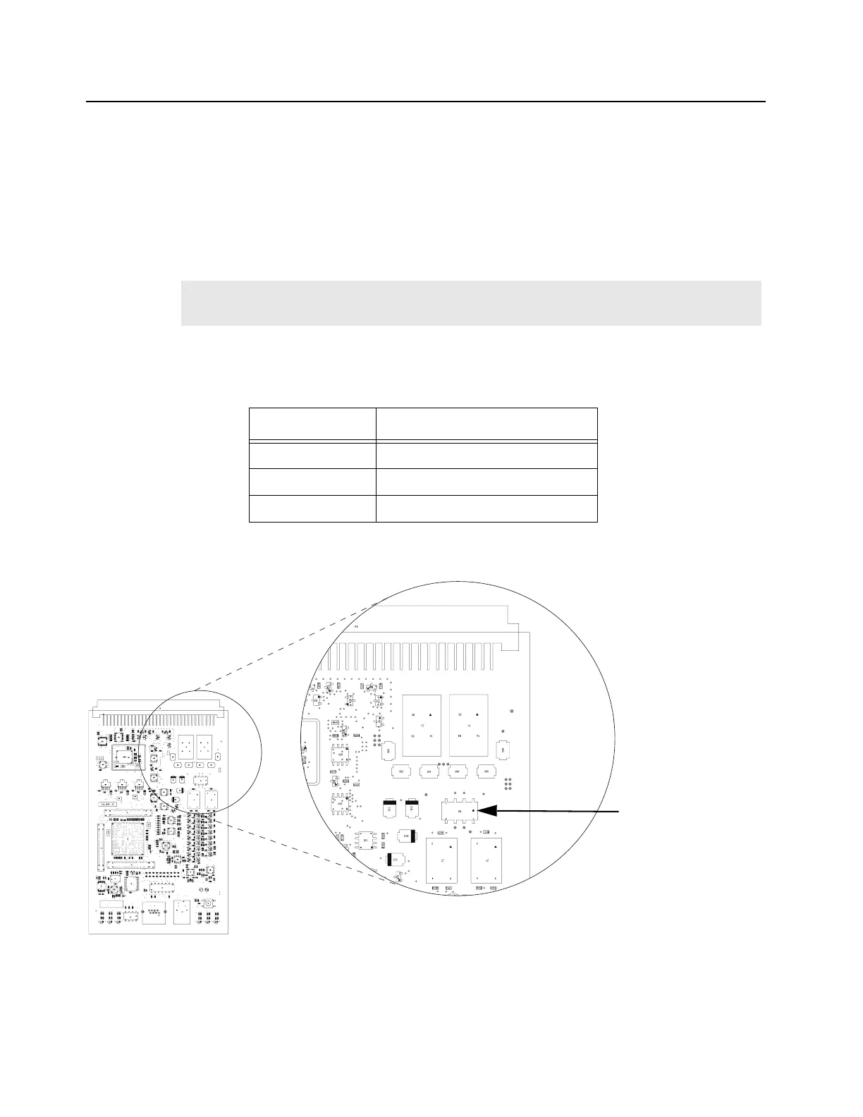
Table 8-3 shows the jumper configuration while Figure 8-1 shows the location of jumpers on the P8
connector for the Wireline Interface Board.
Note
For maximum audio performance, the jumpers should be removed when operating in Tone
Remote Control or no remote control mode.
Table 8-3 Wireline Board Jumper Settings
Header P8
No DC Remote No jumpers installed
2-Wire DC Remote Jumper pins : 5 to 6, 7 to 8
4-Wire DC Remote Jumper pins : 1 to 2, 3 to 4
Figure 8-2 Location of jumpers on the P8 connector
Jumpers
Top (from left to right):
7, 5, 3, 1
Bottom (from left to right)
8, 6, 4, 2
 Loading...


