MTR3000 Third Party Controllers: Phone Patch E-7
E.3.3 Hardware Connections
The connections between the MTR3000 Base Station/Repeater and the phone patch are facilitated
with a multi-conductor cable connected between the J7 MTR3000 25-Pin connector and that of the
phone patch. The connection provides for the following signals:
• Transmit Audio
• Receiver Audio
•PTT
•COR
• 14.2 VDC (see Note)
•Ground
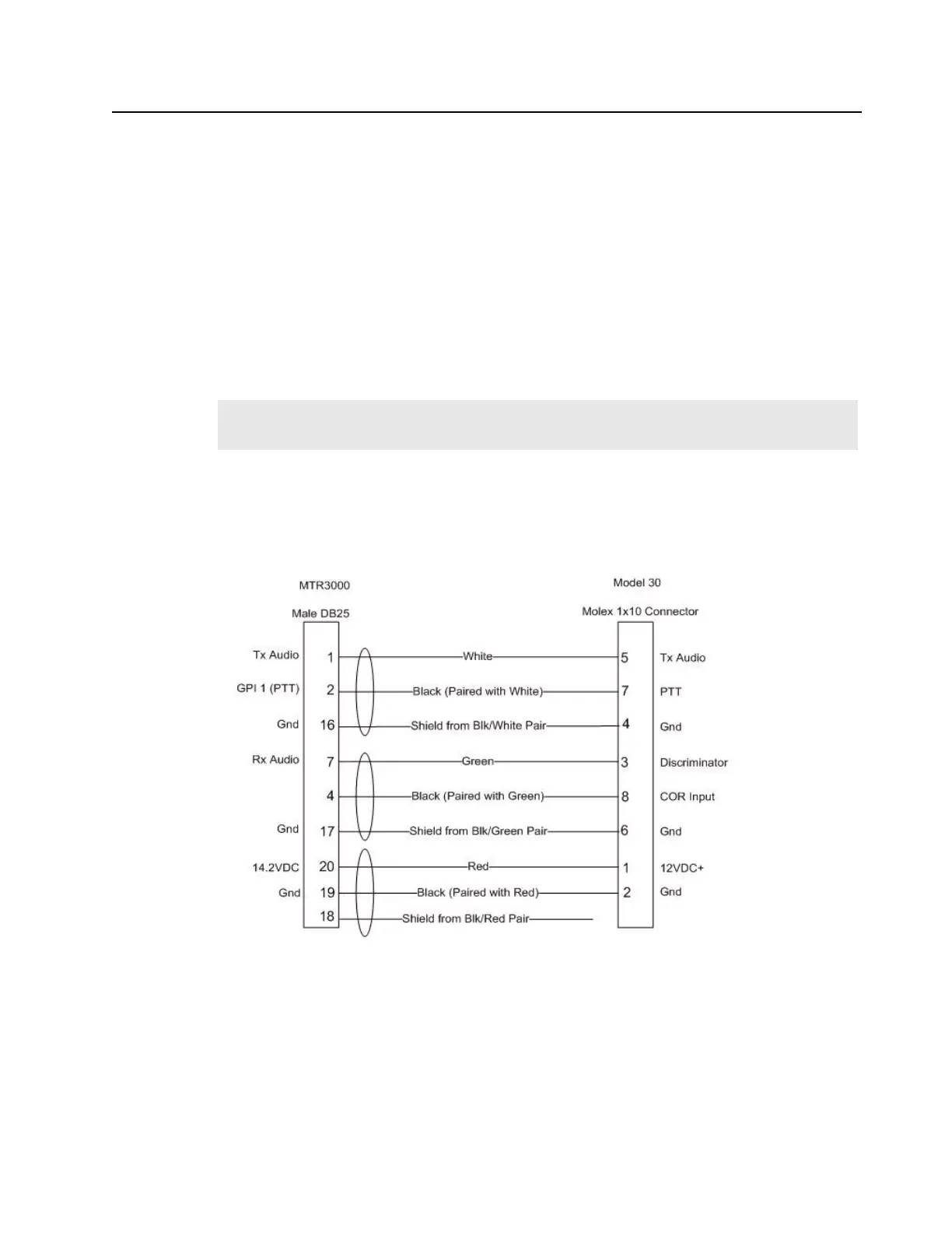
Signal connections are noted in Figure E-2. The MTR3000 Base Station/Repeater connector and
physical Pin locations are noted in the backplane interface board section of this manual. See Zetron
Model 30 manual for its connector and physical Pin locations. The part number for a pre-fabricated
cable is noted in the MTR3000 ordering guide.
Figure E-7 Signal Connections between MTR3000 Base Station/Repeater and Zetron Model 30 Phone Patch
E.3.4 CPS Configuration
The MTR3000 Base Station/Repeater will need to be configured via the CPS application as shown in
Figure E-4 and Figure E-5. More specifically, the affected parameters are as follows:
• Audio Type
- Rx & Tx Filtered Squelch
• Analog Accessory Emphasis
Note
If this connection is used, the external equipment must draw less than 1A. This connection
must be accessed by Pin C32 of connector J5 on an upgraded MTR2000.
 Loading...


