MTR3000 Exciter Module: Specifications 3-3
3.2 Specifications
Table 3-1 shows the specifications of the MTR3000 Base Station/Repeater’s Exciter Module.
3.3 Functional Theory of Operation
The following theory of operation describes the operation of the Exciter circuitry at a functional level.
Refer to Figure 3-2 for the block diagram of the Exciter module.
3.3.1 Functional Overview
3.3.1.1 Synthesizer and VCO Circuitry
3.3.1.1.1 Phase-Locked Loop
The phase-locked loop (PLL) IC receives frequency selection data from the SCM microprocessor
(via the SPI bus). Once programmed, the PLL IC compares a 8.4 MHz (UHF) or
16.8 MHz (800/900 MHz) reference signal (from the SCM) with a divided-down feedback sample of
the VCO output. Depending on whether the feedback signal is higher or lower in frequency than the
8.4 MHz reference, up/down correction pulses are generated. (The width of these correction pulses
depends on the quantitative difference between the 8.4 MHz reference and the VCO feedback.)
The up/down pulses from the PLL IC are fed to a charge pump which outputs a DC voltage
proportional to the pulse widths. This DC voltage is then low-pass filtered and fed to the VCO as the
control voltage.
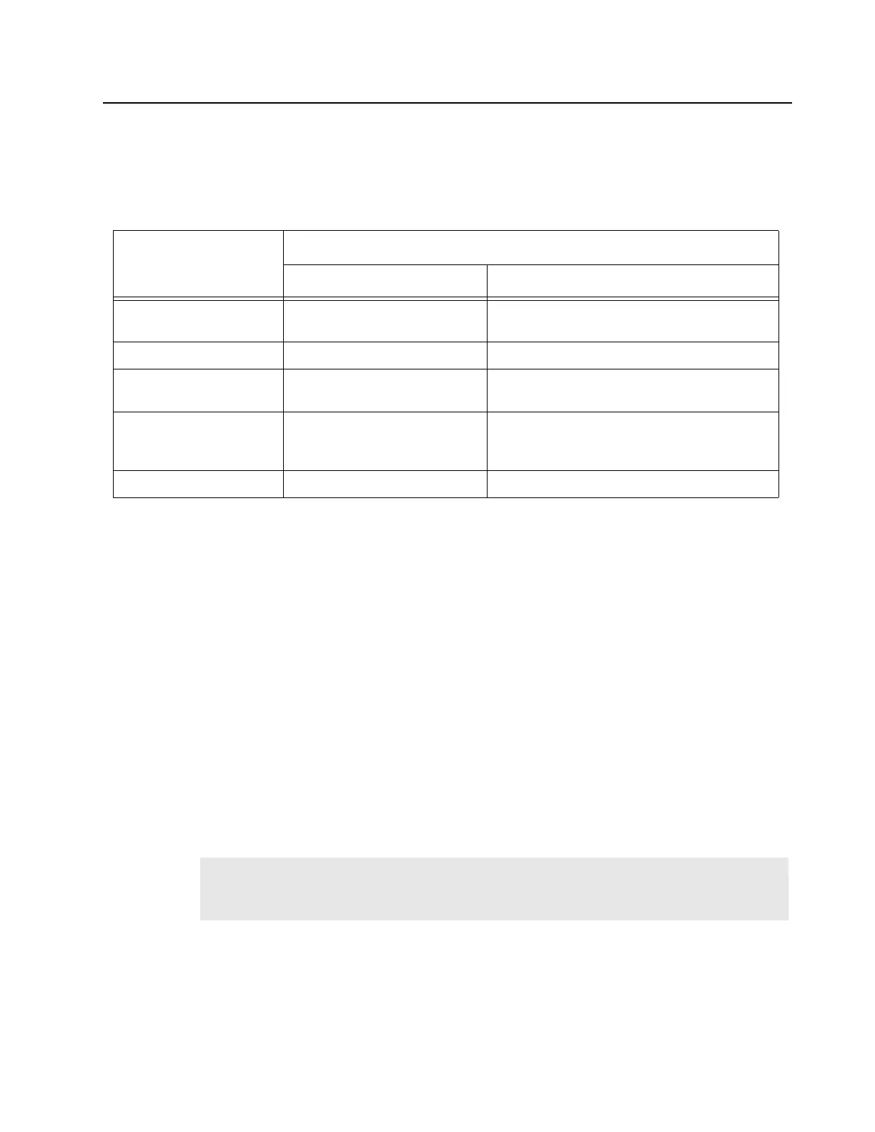
Table 3-1 Specifications of Exciter Module
Parameter
Specification
UHF 800/900 MHz
Frequency Ranges 403–470 MHz (UHF R1) or
450–524 MHz (UHF R2)
851–870 MHz & 935–941 MHz
Electronic Bandwidth Full Bandwidth (UHF R1 and R2) Full Bandwidth (851–870 MHz & 935–941 MHz)
Output Power 10–14 dBm 13–18 dBm (800 MHz),
14–18 dBm (900 MHz)
Current Draw (Maximum) 0.05 A from 14.2 VDC supply
0.15 A from 10 VDC supply
0.1 A from 8 VDC supply
0.05 A from 14.2 VDC supply
0.15 A from 10 VDC supply
0.1 A from 8 VDC supply
Harmonics -20 dBc -20 dBc
Note If a frequency change is requested by the SCM microprocessor, the lowpass loop filter is
momentarily bypassed to accelerate the frequency change (via a SYNTH ADAPT signal
from the SCM).
 Loading...


