MTR3000 Third Party Controllers: Phone Patch E-9
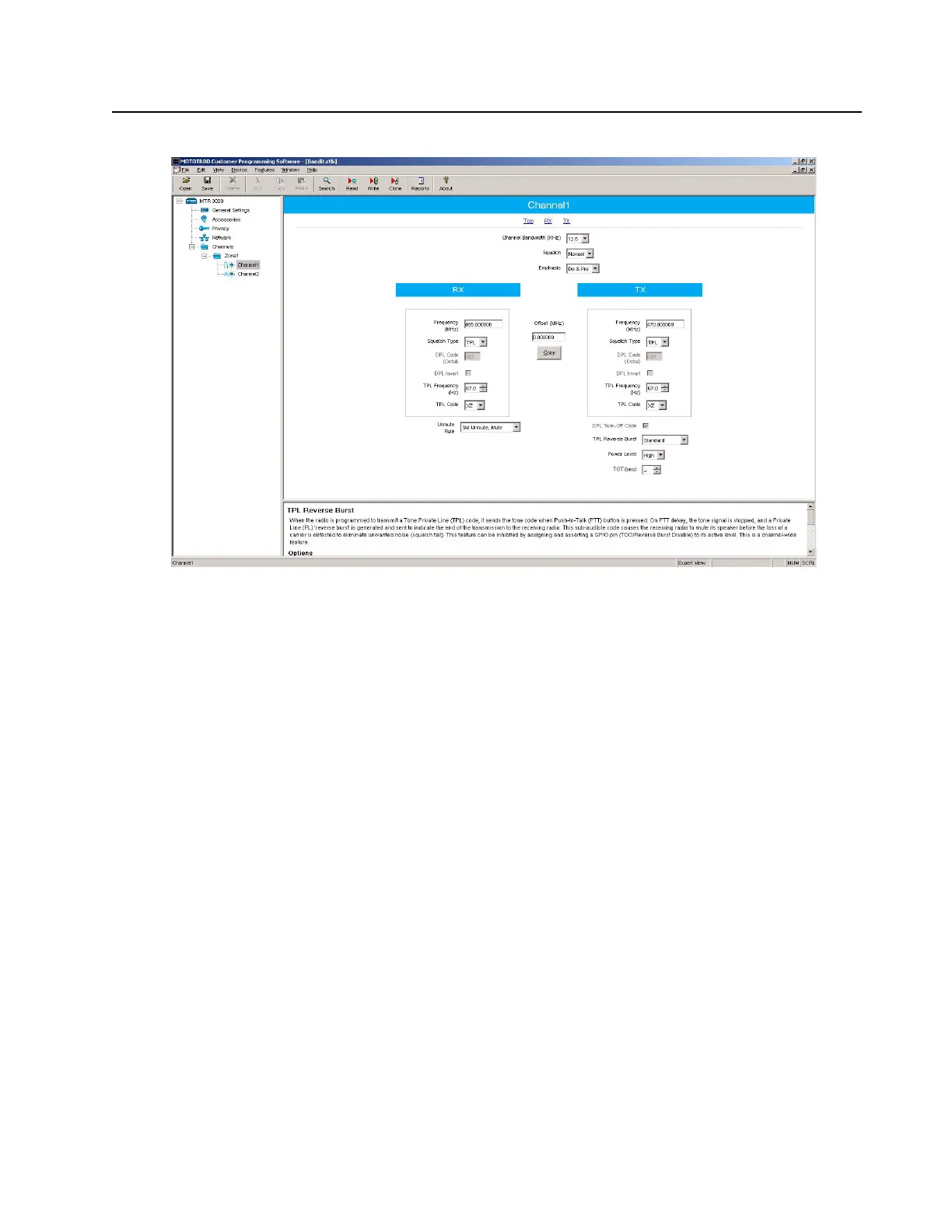
Figure E-9 CPS Configuration for Phone Patch (2 of 2)
E.3.5 Phone Patch Level Settings
The input and output levels should be adjusted per the phone patch’s instructions. The summary
below gives a brief overview of the high level characteristics and phone patch settings for
configuration with the MTR3000.
E.3.5.1 Disc
The MTR3000 Base Station/Repeater’s Receiver audio will yield 330mV rms into 50 kΩ with an RF
input signal deviating at 60% RSD. With the phone patch’s own loading impedance, the “Disc” signal
delivered to the phone patch is at a high enough drive level to leave jumper JP1 in the factory default
position (position A).
E.3.5.2 Tx Audio
The MTR3000 Base Station/Repeater’s transmitter will yield 60% RSD with 80mV rms into the Tx
Audio port. The “Tx Aud” signal delivered by the phone patch is at a high enough drive level to leave
jumper JP3 in the factory default position (position B).
E.3.5.3 CTCSS / DCS DECODE INPUT / COR
Set jumper JP6 to position A, to match the MTR3000’s active low indication of a PL/DPL detect.
Set jumper JP7 to position B, to external squelch indication.
Set jumper JP8 to position C, to match the MTR3000’s active low indication of a COR detect.
 Loading...


