5-10 MTR3000 Station Control Module: Functional Theory of Operation
5.2.11 Front Panel LEDs
For details on this section, refer to Table 1-8.
5.2.12 Supply Voltage Circuitry
The SCM contains on-board regulator and filtering circuitry to generate the various operating
voltages required by the SCM circuitry. The SCM routes +10 V and +8 V from two regulators on the
backplane interface board to the Receiver and Exciter modules. +14.2 V and +5.1 V from the power
supply (via the backplane interface board) are used as sources for the following supply voltage
circuits:
• +14.2 V Regulator Circuitry – input to generate 9.3 V for MAKO, and 5 V analog for the audio
circuit. This regulator also routes 14 VDC to the Receiver and Exciter modules.
• +5.1 V Regulator Circuitry – input to generate the following voltages: 3.3 V, 3.3 V analog,
2.775 V analog, 1.875 V, 1.4 V Core for Tx and Rx OMAP1710, 1.2 V Core for FPGA.
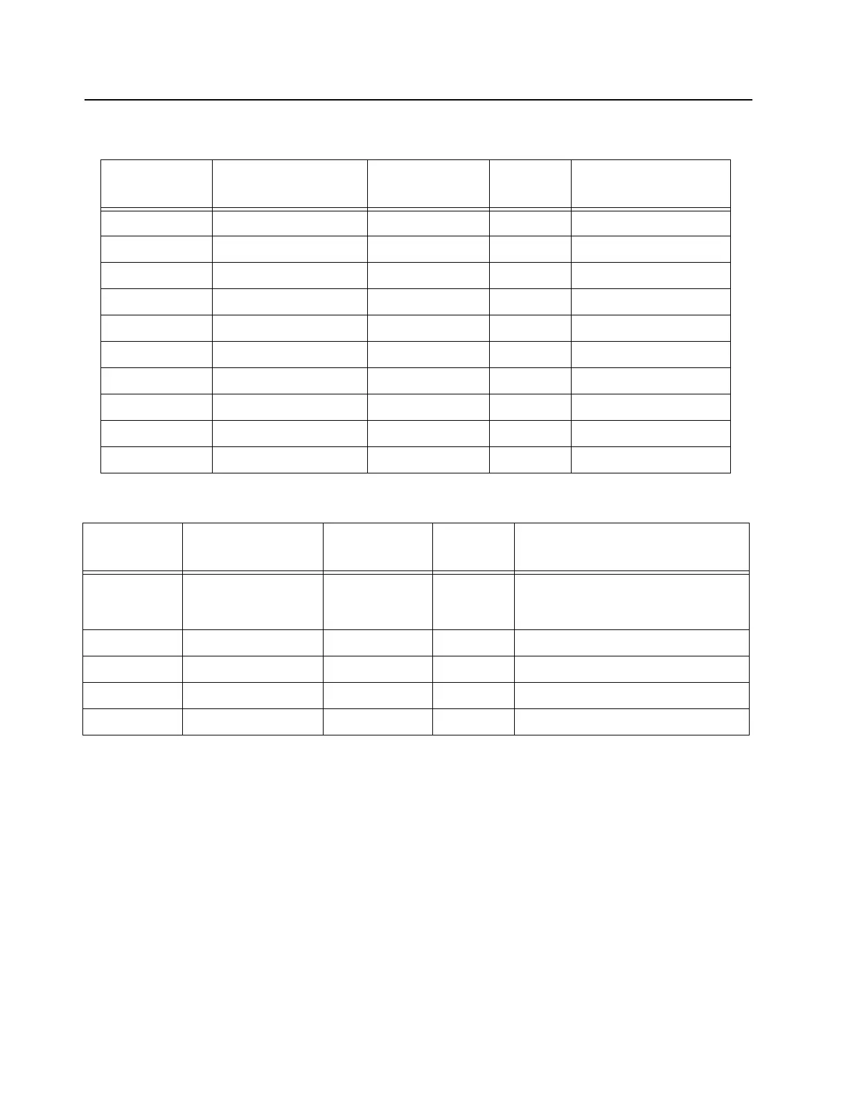
Table 5-8 Station Control Module (SCM) FP Ethernet Connector Pin-out
Pin Number Pin Name I/O
Voltage
Level (V)
Pin Description
1 ENET_TXN_FP Output 5 Ethernet Tx negative
2 ENET_TXN_FP Output 5 Ethernet Tx positive
3 ENET_RXN_FP Input 5 Ethernet Rx negative
4 GND GND GND Ground
5 GND GND GND Ground
6 ENET_RXP_FP Input 5 Ethernet Rx positive
7 GND GND GND Ground
8 GND GND GND Ground
G1 GND GND GND Ground
G2 GND GND GND Ground
Table 5-9 Station Control Module (SCM) FP External Reference Connector Pin-out
Pin Number Pin Name I/O
Voltage
Level (V)
Pin Description
C EXT_REFERENCE Input 5 5 MHz or 10 MHz external reference.
This can be either a sine or a square
wave.
G1 GND GND GND Ground
G2 GND GND GND Ground
G3 GND GND GND Ground
G4 GND GND GND Ground
 Loading...


