12-2 MTR3000 Performance Check or Testing: Verifying Transmitter Circuitry
12.2.3 Verifying Transmitter Circuitry Procedure
1. Connect and set up test equipment by performing Steps 1–5 shown in Figure 12-1.
2. Apply input power (AC or DC) to the base station/repeater. The power supply and PA fans
should both run a few seconds to confirm fan operation.
3. Press the PTT button of the microphone and observe the PA Keyed LED indicator on the
Station Control Module.
• If PA Keyed fails to light, suspect the following:
- Faulty Power Amplifier Module
- Faulty Exciter Module
- Loose or bad Exciter-to-PA RF cable
- Loose or bad PA-to-antenna RF output cable
- Improperly terminated PA RF output cable
- Faulty Station Control Module
- Faulty Power Supply Module
- Faulty Backplane Interface Board
- Faulty Antenna Relay
4. Measure output power by pressing the PTT button and observing reading on an in-line
wattmeter.
• If PA output is not at proper power (as set for particular site), adjust the output power as
described in the CPS online help.
5. If PA output power is proper, set up Aeroflex 3900 Series Communications System Analyzer
for spectrum analyzer display. Press the PTT button and observe the display. The display
should show a single frequency carrier:
• If the display shows multiple carriers evenly spaced about the carrier, suspect a faulty Exciter
module or PA module.
• If the display shows a solid carrier but it is off frequency, suspect the following:
- Faulty Exciter or Station Control Module
- Faulty external 5/10 MHz reference source (if used)
• If the display shows a single carrier moving erratically, suspect:
- Faulty Station Control Module
- Faulty Exciter Module
6. If display is proper, set up Aeroflex 3900 Series Communications System Analyzer to display
modulation. Using the microphone, push the PTT button and speak into the microphone.
Verify that the display shows an audio signal.
Note
In the following steps, suspected faulty modules are ranked in order of most to least
likelihood.
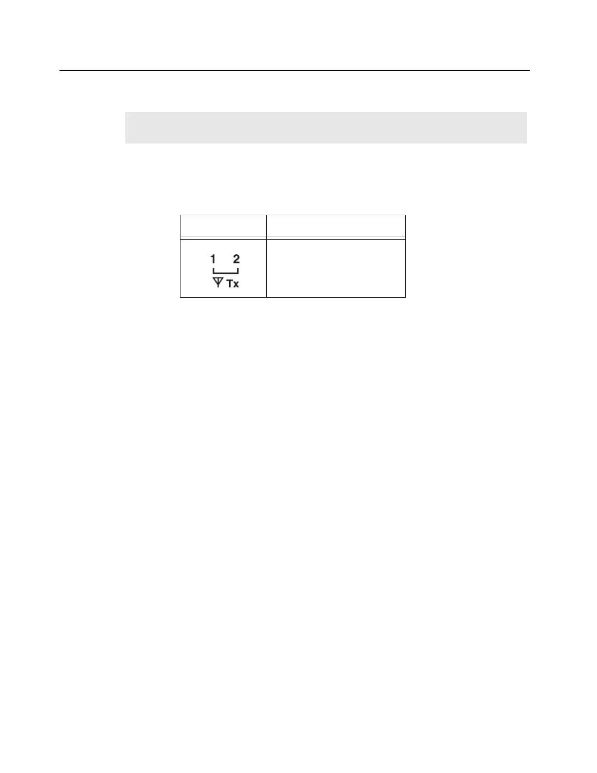
LED
Definition
Tx Slot 1 (for label number 1)
Tx Slot 2 (for label number 2)
 Loading...


