5-8 MTR3000 Station Control Module: Functional Theory of Operation
5.2.10 Front Panel (FP) Connectors
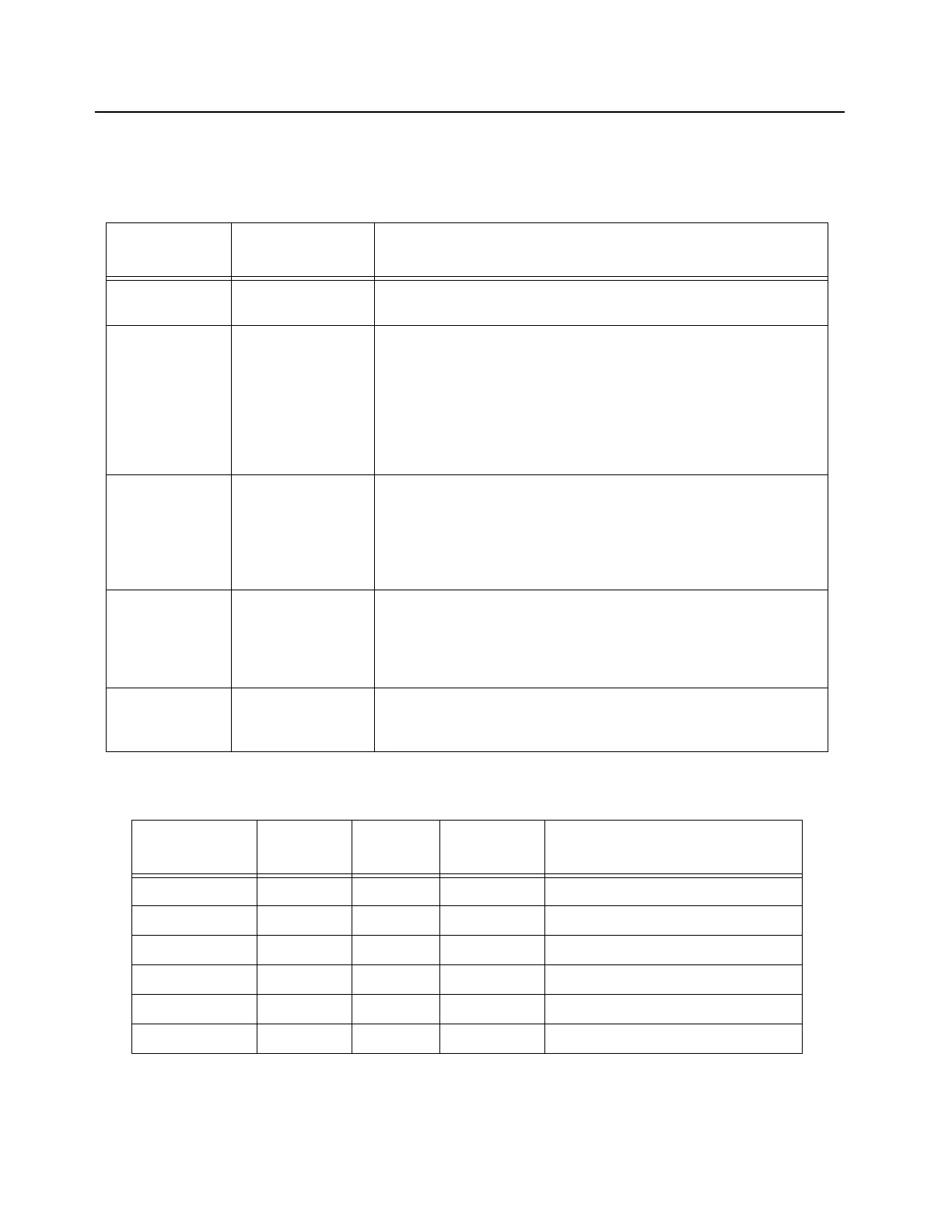
Table 5-4 to Table 5-9 describe the front panel connectors.
Table 5-4 Station Control Module (SCM) FP Connectors
Connector
Name
Connector Type Purpose
Service USB Type B Service Computer connection. This connector is accessible with front
cover in place.VBUS (+5V) is not provided on the USB connector.
Mic RJ45 (8 Pin) Microphone connection. Compatible with microphone GMN6147 (older
model) or GMMN4063. This connector is accessible with front cover in
place.
Note : The Mic port is only supported in analog mode regardless of the
Mic used. For older model of microphone (GMN6147), the 3 control
buttons for speaker volume control, Rx monitor and Intercom control
functions are not supported.
Speaker 4P4C Speaker connection. Compatible with Service Speaker HSN1000
(older model) or HSN1006. This connector is accessible with front
cover in place.
Note : The Speaker port is only supported in analog mode regardless
of the speaker used.
Ethernet RJ45 (8 Pin)
(Vertical)
Network connection to Trunking Controller. The front cover must be
removed to access this connector. An optional extension cable can
also be used to route this input to the rear of the station. Alternatively,
the Ethernet cable can also be routed out through the slots provided in
the front panel.
Ext Ref BNC (Vertical) External reference input. The front cover must be removed to access
this connector. Alternatively, an extension cable can be used to route
this input to the rear of the station.
Table 5-5 Station Control Module (SCM) FP USB Connector Pin-out
Pin Number Pin Name I/O
Voltage
Level (V)
Pin Description
1 VCC VCC 5 Supply Voltage for USB Client mode
2 DM I/O 3.3 Connects to MAKO USB1 transceiver
3 DP I/O 3.3 Connects to MAKO USB1 transceiver
4 GND GND GND Ground
G1 GND GND GND Ground
G2 GND GND GND Ground
 Loading...


