MTR3000 Wireline: Specifications 8-3
8.2 Specifications
Table 8-1 shows the specifications of MTR3000 Wireline board.
8.3 Functional Theory Of Operation
The following theory of operation describes the Wireline board at a functional level. The information
is presented to give the service technician a basic understanding of the functions performed by the
module in order to facilitate maintenance and troubleshooting to the module level. Refer to
Figure 8-5 for the block diagram of the Wireline board.
8.3.1 Functional Overview
8.3.1.1 FPGA
The MTR 3000 Wireline board uses Digital Signal Processing (DSP) techniques to implement all
required remote control functions, filtering algorithms, and audio adjustments. Audio enters and
leaves the board as analog, but is converted to digital in the interim for processing.
The FPGA is responsible for handling all audio processing functions. It accepts digital audio data
from the CODEC, applies the required filters and algorithms, and sends the resulting audio samples
back to the CODEC to be converted back to analog. In addition to its audio processing functions, the
FPGA also manages CODEC configuration, generates the CODEC master clock, drives and
interprets backplane interface board GPIO signals, interprets decoded DC Remote Control signals,
and services configuration requests from the Station Control Board via the backplane interface board
SPI interface.
8.3.1.2 CODEC
The Digital-to-Analog and Analog-to-Digital conversions for both the Tx and Rx paths are handled by
a single stereo CODEC. The CODEC converts analog audio to digital samples which are sent to the
FPGA for further processing. The FPGA will then return modified digital samples to the CODEC to be
converted back to analog.
The CODEC is configured by the FPGA via an I2C interface. The FPGA synthesizes the CODEC
master clock from the board’s on-board oscillator. In return, the CODEC will generate the bit clock
and word clock used to transfer digital audio data between the CODEC and FPGA.
Two-wire and Four-wire Tx audio use different analog input pins on the CODEC. The CODEC will
select the appropriate input based on the “Wire Mode” setting in the CPS tool. When operating in
4-wire mode, the 2-wire Tx audio path is automatically disconnected from the CODEC input using an
analog switch. This helps to reduce crosstalk and improve audio performance.
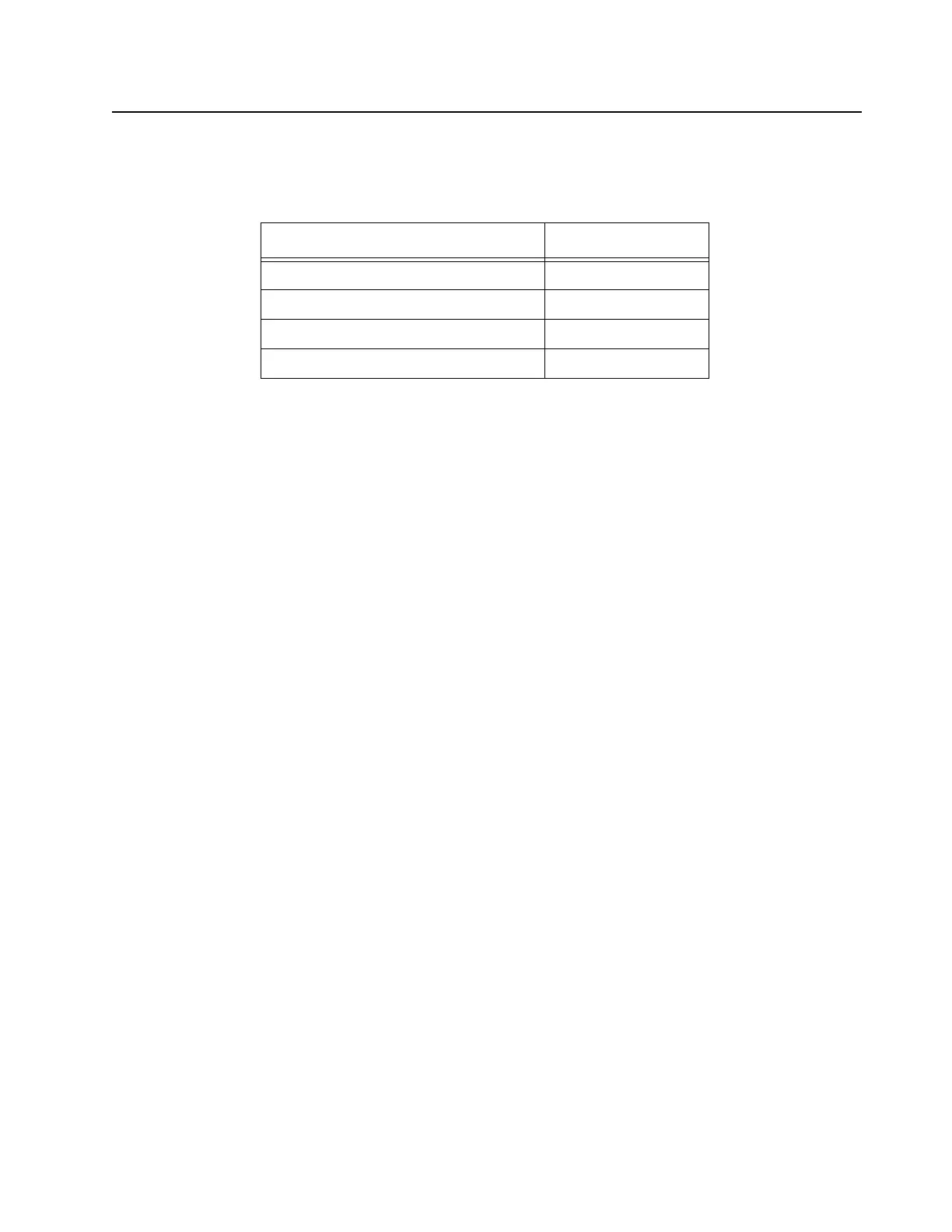
Table 8-1 Specifications of Wireline board
Parameter Specification
Wireline Transmit Level +10 to -30 dBm
Wireline Receive Level +7 to -30 dBm
Return Loss > 20 dB
Distortion Introduced < 0.5%
 Loading...


